![]()
User Manual
![]()
User Manual
![]()
User Manual
Thank you for choosing the MICROQ, a product in the QuantusSeries range.
This document will familiarise you with the MICROQ’s functionality. It is a comprehensive guide on how to use the device, from switching on and setting up the system, to measuring parameters with modular signal conditioning channels.
Herein you will also find information about the DOCKQ and External MICROQ Battery, additional products typically purchased with the MICROQ.
Note: read this carefully before using your MICROQ for the first time.
Note: Pay attention to your surroundings while handling the MICROQ, such as:
The MICROQ has non-slip feet and can be used on dry, hard and flat surfaces. Take care to secure it properly during non-stationary use e.g. inside a vehicle.
The MICROQ has been designed to withstand rough conditions. However, it is a sensitive and complex electronic instrument which must be handled with care.
The MICROQ has been provided with reasonable ESD protection. However, antistatic precautions must still be followed to ensure components remain protected against an electrostatic discharge.
Do not use a cable, power supply, or any other MICROQ component if damaged.
The MICROQ should not be operated or stored in or near flammable (fumes, gasses, liquids, etc), excessively harsh (corrosive, ambient temperature above 50 °C, radioactive, hydraulic fluid, etc) or excessively damp environments.
Note: The system may heat up after prolonged use. Carefully check the surface temperature before handling the device further.
The radiated output power of the MICROQ is within acceptable radio frequency exposure limits and is intended to be used 300 mm away from a human operator.
MICROQ Batteries are shipped partially charged. When powering the MICROQ for the first time, be sure to fully charge the Internal Battery before switching on the device.
The MICROQ Battery’s specified operating temperature range is -20 °C to 60 °C. > Note: battery capacity decreases substantially in low temperatures and cold climates. The MICROQ may not operate, and is not specified, for use in temperatures below -20 °C or above 60 °C.
Overtemperature shutdown functionality is included in the MICROQ firmware to protect against overheating. The overtemperature protection in the MICROQ firmware periodically measures the temperature of each QModule and the controller present in the system to determine the maximum temperature value (MaxTemp) inside the MICROQ. The MaxTemp value initiates the following actions:
| Temperature Range | Action |
|---|---|
| MaxTemp < 80 °C | No action |
| 80 °C < MaxTemp | At 80 °C the system will perform a normal system shutdown |
It is recommended that the system be cleaned using a damp lint-free cloth.
Mecalc supports environmentally sound recycling. Recycle or dispose of MICROQ Batteries through a reputable service provider or contact your supplier (Mecalc Representative or OEM Partner) for assistance. This is also applicable to any other broken or unused components.
The MICROQ contains a built-in Li-Ion battery and is typically purchased with an additional battery. > Note: take note of regulations concerning the transportation of these Li-Ion batteries see “Transport Regulations” for more information. For additional advice concerning the transport of your MICROQ and/or MICROQ Batteries, please contact your supplier.

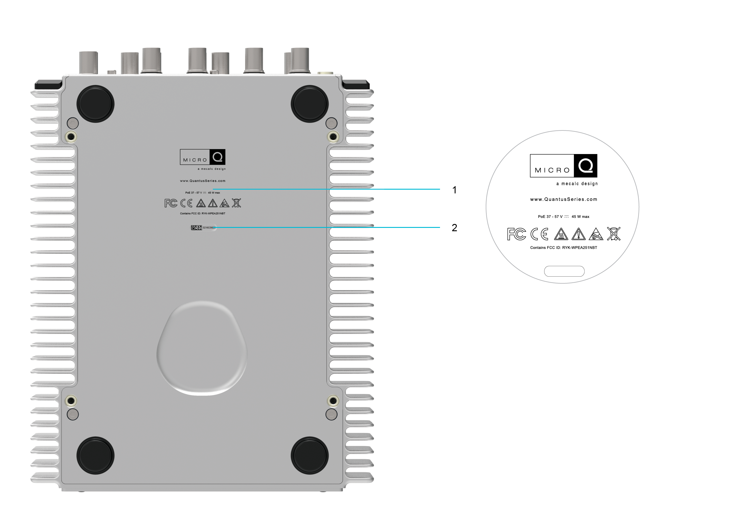
This symbol indicates the user should take note of warnings provided on the MICROQ, DOCKQ and External MICROQ Battery. It can be found at the back of those devices.

This symbol indicates the MICROQ, DOCKQ and External MICROQ Battery are compliant with the WEEE (Waste Electrical and Electronic Equipment) Directive and adhere to policies that promote efficient and environmentally sound recycling. For more information, go to “Recycling Regulations”.

This symbol indicates it is mandatory to recycle the Internal/External MICROQ Battery when it becomes waste. The 00 indicates that the maximum amount of metal contained in the positive electrode is Cobalt and that there are no metals which hinder the recycling of the main metals.
The MICROQ needs to be handled with care after prolonged use. See “Precautions” for more information

Users of the MICROQ and DOCKQ need to adhere to antistatic precautions while using these devices.

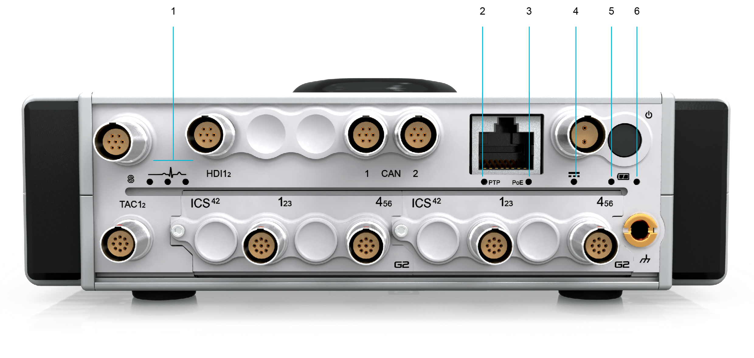
Make sure to earth the MICROQ when used in environments where electrical shock is likely to occur. This symbol can be found on the front panel of the MICROQ. See “Front View” for more information.


Products discussed in QuantusSeries Product User Guides comply with Part 15 of the FCC Rules. For more information, see “US Federal Communications Commission (FCC)” under “Electromagnetic Compatibility Regulations”.

MICROQs with the MIC Technical Conformity mark are fitted with built-in Wi-Fi which has been certified for use in Japan.
The products referred to below are discussed in QuantusSeries Product User Guides: the MICROQ, the DOCKQ, the MICROQ Battery (Internal/External) and QModules (modular signal conditioning channels).
Products discussed in QuantusSeries Product User Guides comply with safety requirements set out in the following:
Products discussed in QuantusSeries Product User Guides do not exceed the chemical concentration limits imposed by the following EU directives:
Products discussed in QuantusSeries Product User Guides do not contain any “substance of very high concern” (SVHC) above a concentration of 0.1% weight of the product, as per Regulation (EC) No 1907/2006 of the European Parliament and the Council of 18 December 2006 concerning the Registration, Evaluation, Authorisation and Restriction of Chemicals (REACH).
Products discussed in QuantusSeries Product User Guides do not contain any mercury, mercury compounds or mercury relays.
Products discussed in QuantusSeries Product User Guides do not contain any substances listed in Class I or Class II Specified Chemical Substances under the Japan Chemical Substances Control Law (CSCL).
Warning: This equipment is compliant with Class A of CISPR 32 / EN 55032. In a residential environment this equipment may cause interference.
When using a Hama 00047771 Surge protection adaptor (overvoltage protection) on the MICROQ PoE mains power supply, the MICROQ complies with Directive 2014/53/EU of the European Parliament and of the Council of 16 April 2014 on the harmonization of the laws of the Member States relating to the making available on the market of radio equipment, specifically:
Note that when using a commercial grade PoE Injector (or Adaptor) to power the MICROQ, ensure that there is a surge protection device installed in the facility where it is used. Alternatively plug in a local surge protector at the mains socket where the PoE Injector is used. This is not required for an industrial grade PoE Injector.
The following harmonized standards and technical specifications have been applied:
Products discussed in QuantusSeries Product User Guides comply with Part 15 of the FCC Rules. Operation is subject to the following conditions: 1. this device may not cause harmful interference, and 2. this device must accept any interference received, including interference that may cause undesired operation.
MICROQs with the MIC Technical Conformity mark are fitted with built-in Wi-Fi which has been certified for use in Japan.
Requirements regarding the transportation of the MICROQ and MICROQ Batteries have been compiled based on the current IATA (International Air Transport Association) Dangerous Goods Regulations of 1 January 2019.
It is important to note that regulations are subject to change without notice. > Note: Contact your courier, shipper or travel agent for up to date regulations.
MICROQ and MICROQ related products which need to be disposed of can be sent back to your supplier free of charge, as required by Directive 2012/19/EU of the European Parliament and Council of 4 July 2012.
Mecalc’s Responsible Sourcing of Raw Materials Policy
Mecalc believes in ethical and responsible business practices and is committed to promoting economic, environmental and social justice at all levels of our supply and manufacturing processes.
As part of this commitment, we:
The products described in this manual are not designed, developed, or intended for military use. They are not included on the United States Munitions List (USML) as defined under the International Traffic in Arms Regulations (ITAR), 22 CFR Parts 120–130.
All products are classified as Commercial Off-The-Shelf (COTS) items. Additionally, these products are regulated under the Export Administration Regulations (EAR) and are classified under Export Control Classification Number (ECCN) 3A992.a. This classification applies to general-purpose electronic devices intended for civilian and industrial applications.
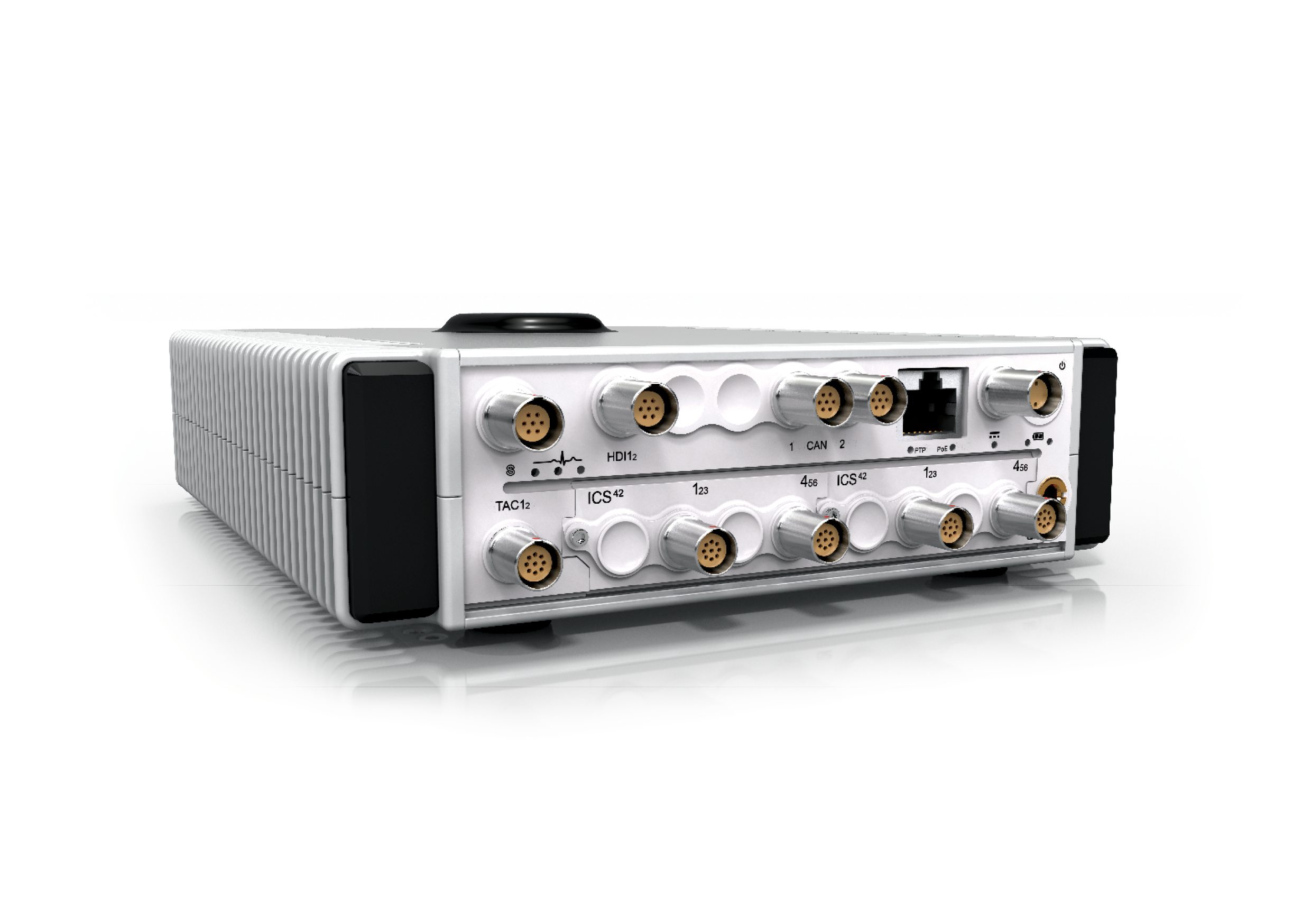
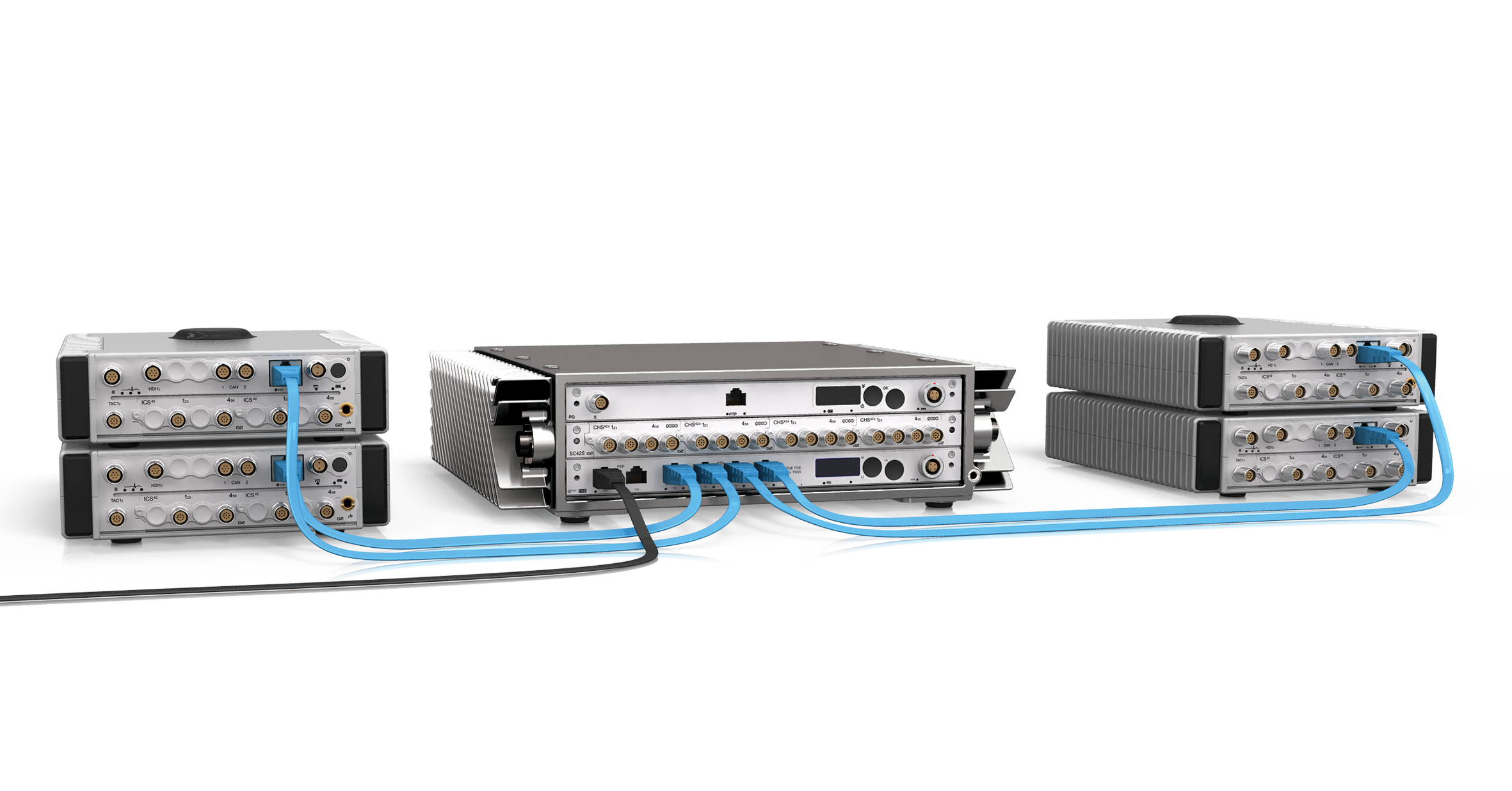
The MICROQ is a compact high quality 2-18 channel data acquisition system which measures electrical and physical quantities. It is cloud capable and designed for portable, troubleshooting and complex laboratory applications with built-in and modular signal conditioning channels, as well as PoE, battery and SSD.
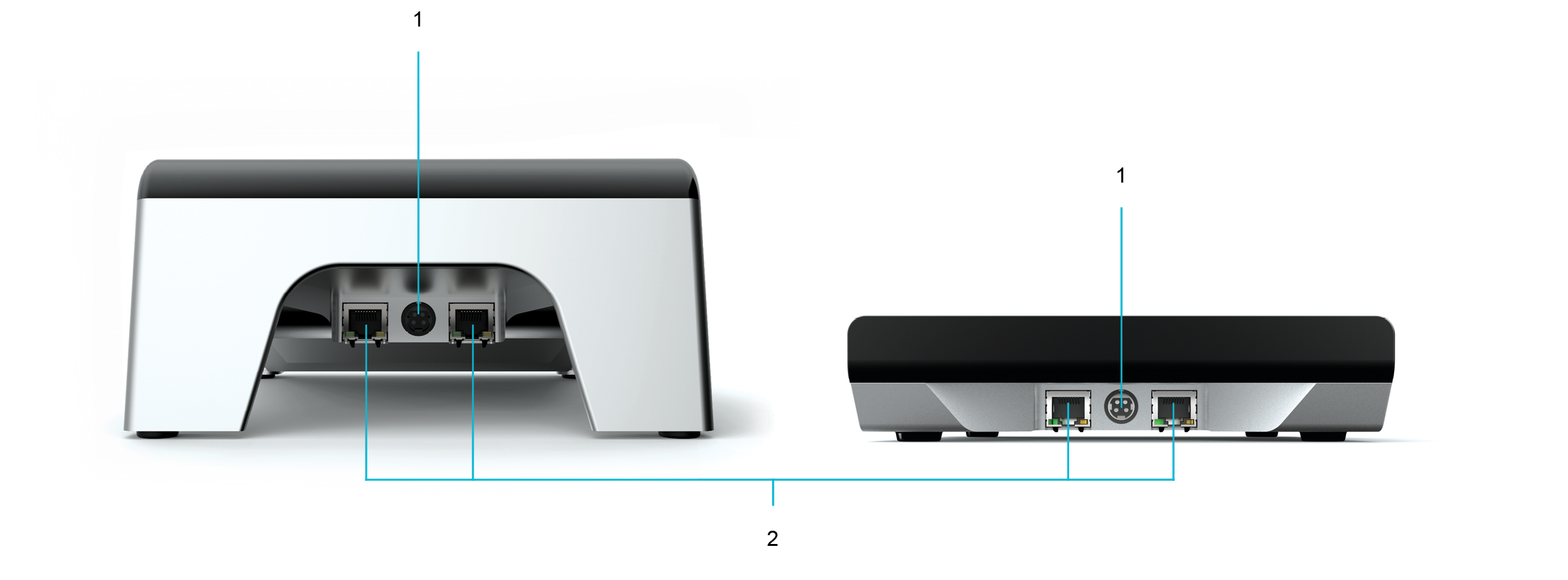
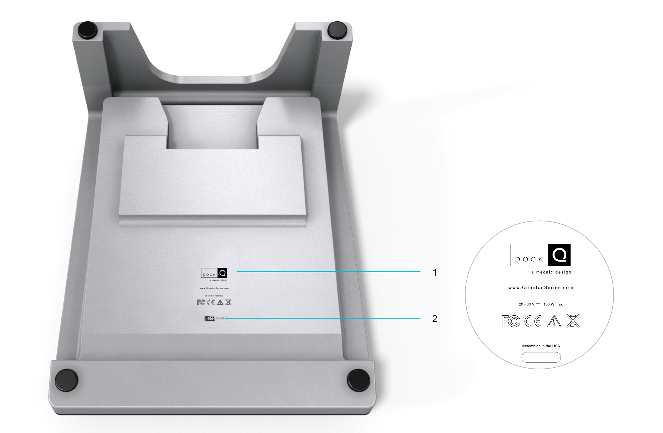
The DOCKQ is a maintenance station which charges MICROQ Batteries, both Internal and External see below. It also connects to a network via Ethernet, allowing seamless integration of your workflow when docking your MICROQ into the DOCKQ Maintenance Bay.
Two DOCKQs are available, the DS10 and the DS20. Both the DS10 and DS20 have the same networking and charging capabilities. The DS20 has been designed for office or laboratory use. The DS10 is easy to transport and can be used in an office or laboratory environment as well as when off-site measurements need to be conducted.
Both Internal and External MICROQ Batteries are Li-Ion batteries, each providing 40 Wh of power.
The Internal MICROQ Battery is a built-in battery, providing from 1 - 2 hours operation, depending on the MICROQ’s configuration.
The External MICROQ Battery can be attached to the MICROQ for longer operation time. Multiple External MICROQ Batteries can be hot swapped for all day operation.
To ensure Li-Ion batteries are functioning at full capacity, it is recommended they be replaced every three years.
Note: The features and specifications in this User Manual may not be included based on the software package utilized with the MICROQ.
The MICROQ front panel contains two Module slots that support a variety of interchangeable Signal Conditioning channels (QModules), which can be purchased separately and then added and/or swapped as the need arises. These QModules are packaged in a robust aluminium casing so as to optimize size and thermal performance, as well as to provide electronic protection.
All QModules include the following features:
Available Analog QModules include:
MICROQs can be powered through either DC Power or Power over Ethernet (PoE). Optional built-in battery power is also available.
The MICROQ will draw power, from whichever sources are connected and ready for use, in the following order:
If all possible power sources are connected, only DC Power will be used to power the MICROQ. DC Power will have to be disconnected for the MICROQ to be powered using PoE or battery power. All other power sources need to be disconnected for the MICROQ to use its battery power (External, then Internal).
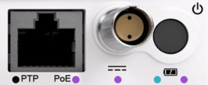
Note: Each power source status is indicated by a status LED.
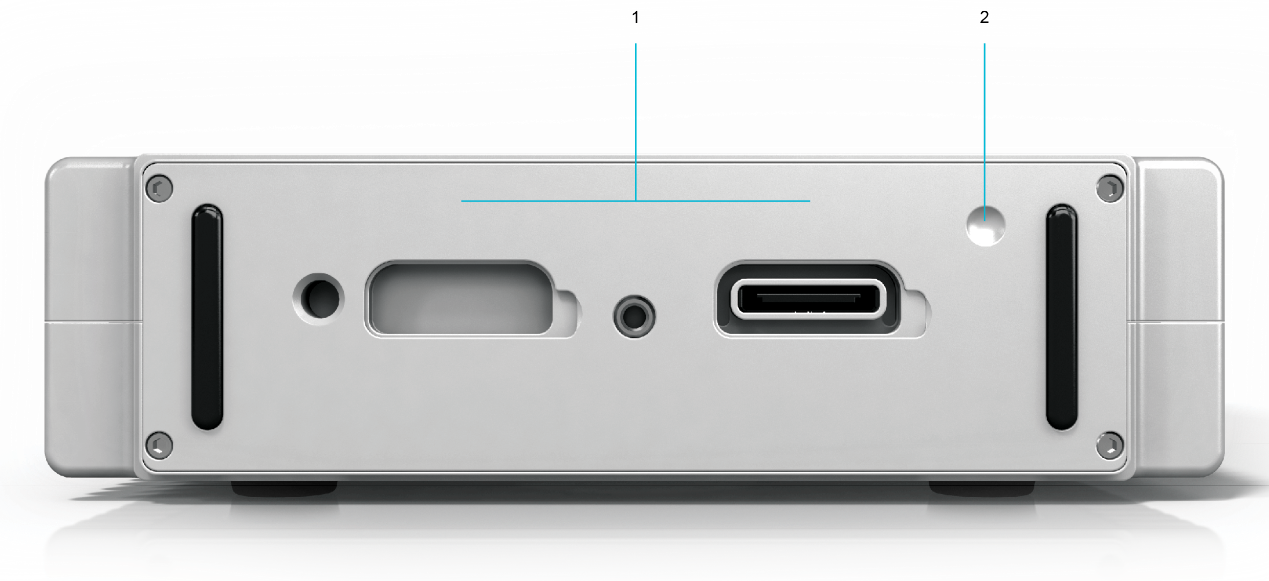
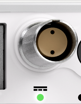
The MICROQ can be powered with DC Power using the LEMO® connector next to the On / Off switch on the front panel. The table below provides a summary of the DC Power specifications:
| Category | Specification |
|---|---|
| Connector | LEMO® EHG.0B.302 |
| Input Voltage Range | 10 - 30 VDC |
| Power required | Up to 40 W |
| Recommended Power Supply | Mean Well GST120A24 |

When powering your MICROQ with the recommended Mean Well AC/DC Power Adaptor, connect power by doing the following:
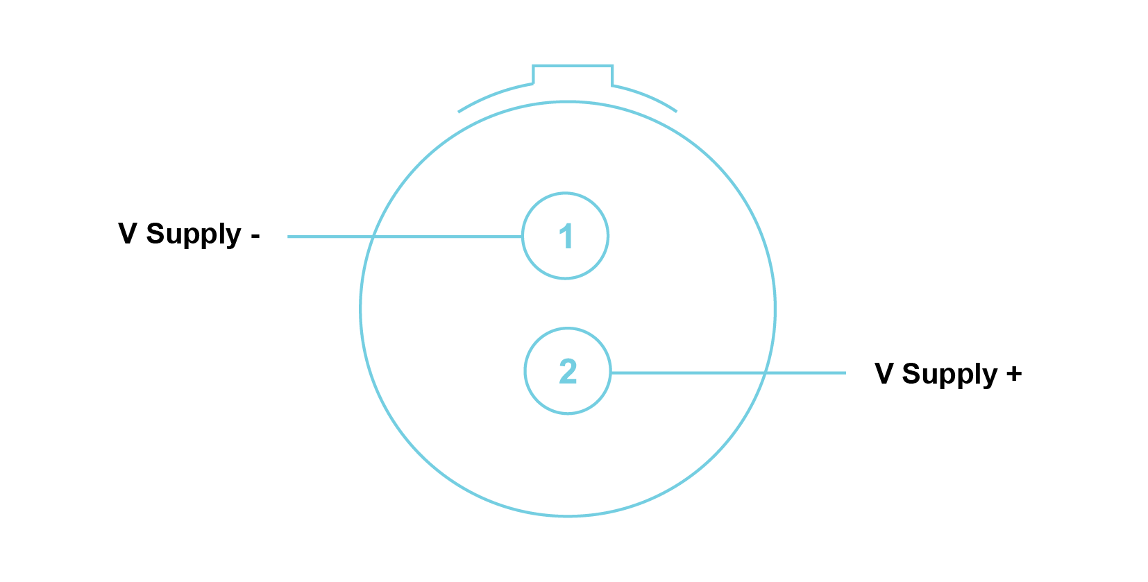
Note: Connector is shown as if looking into the front panel’s connector or at the rear of the cable’s connector.
Note: Additional DC Power cables and accessories are available, please contact your supplier for more information.
The MICROQ can be set up and powered via IEEE 802.3 PoE. In order to facilitate this, a PoE Injector is supplied for cases where the device does not require industrial surge protection (e.g. in an office environment).

When powering your MICROQ with PoE, connect power by doing the following:
Warning: Beware of ground loops that could be created through the shield of the shielded Ethernet cable.
Note: The LED might change colour for reasons not related to PoE status. For example, after a few seconds the LED might change to solid green to indicate the power (charge) status of the MICROQ Battery.
The table below provides a summary of the MICROQ’s PoE specifications and may serve as a reference when choosing the right PoE Injector for a specific measurement application:
| Category | Specification |
|---|---|
| Design based on PoE standards | 802.3at Type 2, LTPoE++ |
| Connector | RJ45 |
| Input Voltage Range | 42 - 57 VDC |
| Power source required | Up to 40 W |
When choosing the right PoE Injector one should also consider the potential power consumption of specific system configurations (types of Modules and/or sensors in operation, whether Wi-Fi has been enabled, whether local data storage is being used, etc.), as this would directly influence which PoE Injector would be most appropriate for your MICROQ’s operational requirements.
Note: If you intend to use PoE in an industrial environment, request advice from your laboratory manager regarding which third party PoE Injector would be most appropriate. Additional options, including external solutions for battery PoE Injectors are available. Feel free to contact your supplier for more information.
The MICROQ is optionally equipped with a built-in Internal Battery which allows you to fully power your MICROQ for 1 - 2 hours, depending on the system’s configuration.
The External Battery can be attached to the MICROQ in order to extend operation time by an additional 1 - 2 hours, depending on your system’s configuration. Hot-swapping External Batteries can increase uninterrupted operation time significantly.

When being powered by Internal and External Batteries, the MICROQ will draw power from the batteries in the following order:
It is important to note that the External Battery does not charge the Internal Battery. Depleted Internal and External Batteries will need to be charged with DC Power, PoE or by docking into one of the DOCKQ bays.
The MICROQ comes standard with both DC Power and PoE. These sources can charge Internal / External Batteries if the need arises. When using Internal and External Batteries to power the MICROQ, DC Power or PoE can be used to charge both of them simultaneously (while the MICROQ is switched off). DC Power will take priority if both DC Power and PoE are present. The battery (Internal or External) with the lowest charge level will be charged first. Once both batteries have equal charge levels, they will be charged simultaneously.
Note: Charging of the Internal or External Battery takes place only when the MICROQ is switched off. The temperature range of the battery has to be between 0 °C and 45 °C for it to charge.
Use your DOCKQ to charge your External Batteries and/or your MICROQ Internal Battery. The DOCKQ facilitates hot-swapping and helps extend uninterrupted portable operation time.
To charge your External Battery, dock it into either one of the DOCKQ bays. Make sure you align the connectors on the External Battery with the connectors in the docking bay.
Before switching on the MICROQ, make sure it is connected to DC Power or PoE (or contains a sufficiently charged battery).
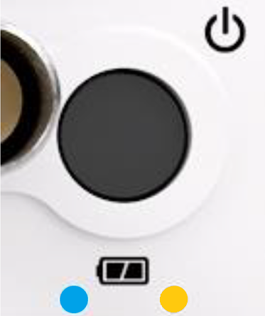
Switch on the MICROQ by pressing and holding down the Power On / Off button until the PoE and Battery LEDs (and DC Power LED if connected) turn solid blue.

Switch off the MICROQ by pressing and holding down the Power On / Off button until the PoE and Battery LEDs (and DC Power if connected) turn red, indicating the MICROQ is shutting down. This will take about one second. Release the button once the LEDs turn red.
The system should take about five seconds to power down. If the shutdown sequence has been initiated after a measurement has begun (and data is still being written to the SSD), the system shutdown sequence will take longer than five seconds.

Note: Do not switch off the MICROQ by disconnecting the power supply. This could result in hardware damage. Additionally, disconnecting the power supply while the MICROQ is running (without MICROQ Batteries with sufficient power levels) could result in measurement data loss and/or hardware damage.
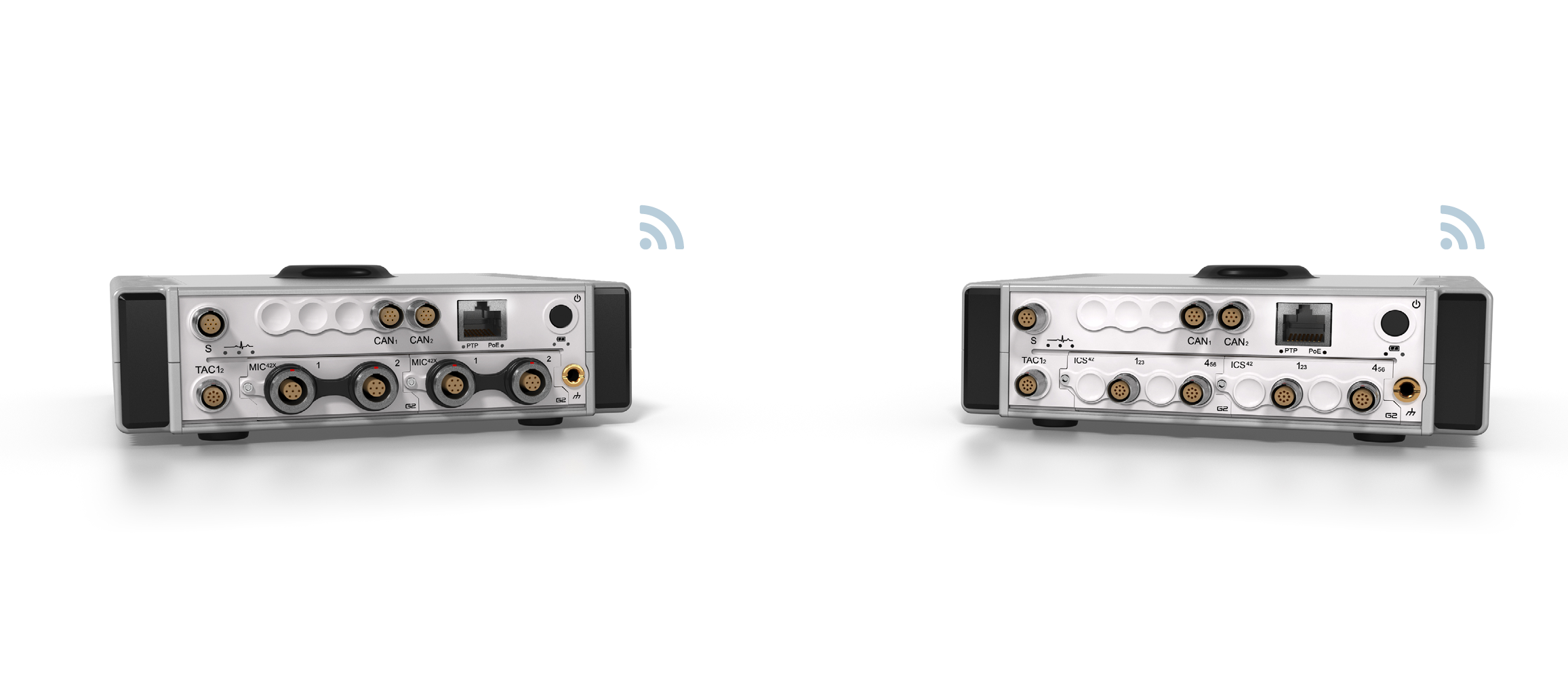
The MICROQ can be connected to a Notebook / PC / network / smart device through Ethernet and/or Wi-Fi.
A built-in 2 MIMO streams IEEE 802.11b/g/n Wi-Fi network interface is available on the MICROQ. The Wi-Fi network interface can be used where truly mobile operation of the MICROQ is required.
The default configuration for the MICROQ Wi-Fi interface is:
Connect to the MICROQ with your compatible Wi-Fi device using the SSID mentioned above. To test connectivity, use the default IP address as the URL in a web browser, for example, http://192.168.2.204.
The default mDNS name may also be used in compatible web browsers, for example, http://Quantus_1234S5678.local.
The browser should then display the MICROQ’s “System Overview” page. The MICROQ’s start-up Wi-Fi interface configuration parameters can be edited in the Web Server’s network setting configuration pages.
Effective Wi-Fi data streaming rates of up to 2.7 MB/s can be achieved with your MICROQ. > Note: that your MICROQ Wi-Fi connection performance is highly dependent on its connection settings, as well as environmental factors including (but not limited to) distance, interference and shared bandwidth.
Note: When configuring the Wi-Fi interface, the settings for “Country”, “IP address” and “Subnet mask” might be different depending on the country in which you are setting up the device.
A Gigabit Ethernet connection (1000 BASE-T) is available on the MICROQ’s front panel that can accept compatible Ethernet cables. When using Ethernet on the MICROQ use only a CAT5e UTP cable. This will ensure the correct screening of signals throughout the length of the cable.
The default configuration for the MICROQ Ethernet interface is:
To use the Ethernet interface, simply plug in an Ethernet cable. The MICROQ will automatically detect the Ethernet cable and initialize it as the primary network interface. Use a Gigabit Ethernet enabled link partner (network device or PC) for best performance.
To test connectivity to the MICROQ, use a web browser that supports mDNS and enter the URL “http://Quantus_1234S5678.local” (replace “1234S5678” with the Serial Number of the MICROQ).
The browser should then display the MICROQ “System Overview” page. The MICROQ’s start-up Ethernet interface configuration parameters can be edited in the Web Server’s network setting configuration pages.
Once booted, the User Interface can also be used to display the system’s IP address. The MICROQ Web Server can then be used (with the IP address as the URL) to make modifications to the network set-up.
Gigabit Ethernet over copper (1000BASE-T) connections allow for cable lengths of up to 100 m. If a longer connection distance is required, active repeaters need to be used at each 100 m interval.
Note: Shielded network cables must be used with all MICROQs.
The MICROQ Web Server is used to display system status information or make changes to specific configuration parameters. The following parameters can be viewed / customised via the Web Server:
Bridged mode – allows the LAN and Wi-Fi to share the same IP address, enabling network traffic to be streamed from Wi-Fi to LAN and vice versa.
Docked mode - additional network interface which is enabled only when the MICROQ is docked in the DOCKQ.
Indicates Battery Power Level, System Status, Application Status and Network Status:

Indicates Initialization Level, Network Activity Status and Battery Status:
Indicates an Upgrade Status or Battery Power Level:
Indicates a System Error:
Indicates an Upgrade is in progress:
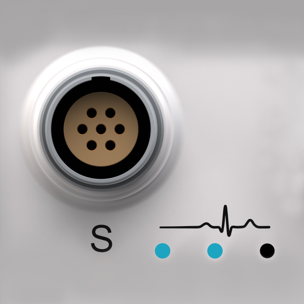
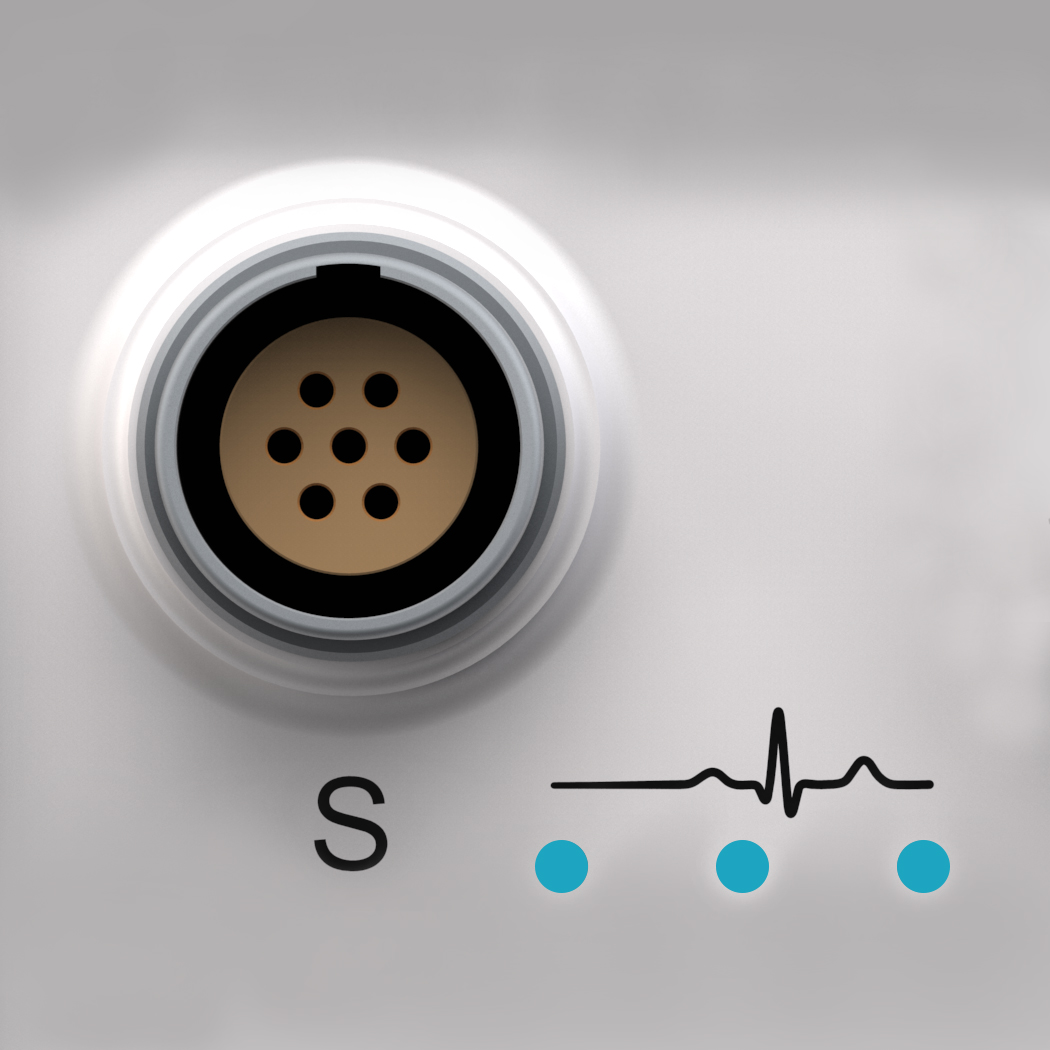
These three blue LEDs indicate the progress of system initialization (1 - 3). Each LED will blink and then turn solid blue until all three LEDs are on, indicating that initialization is complete.
The LED sequence will typically take place in the following order:
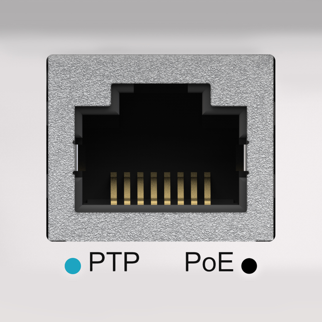
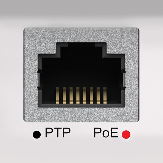
Blue indicates the Ethernet cable is connected. Flashing blue indicates activity on the Network.
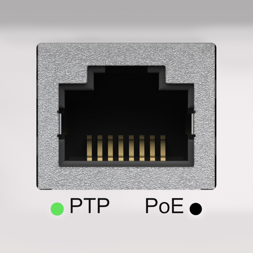
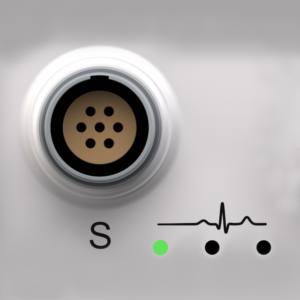
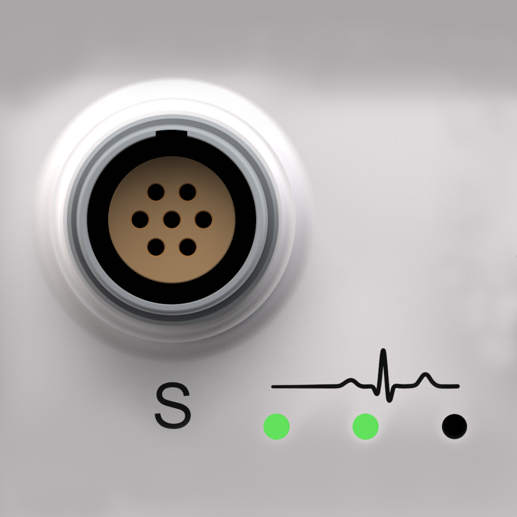
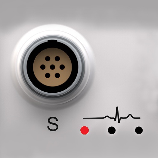
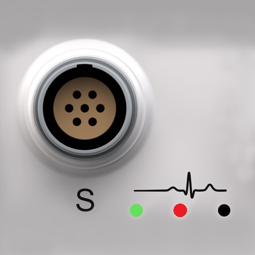
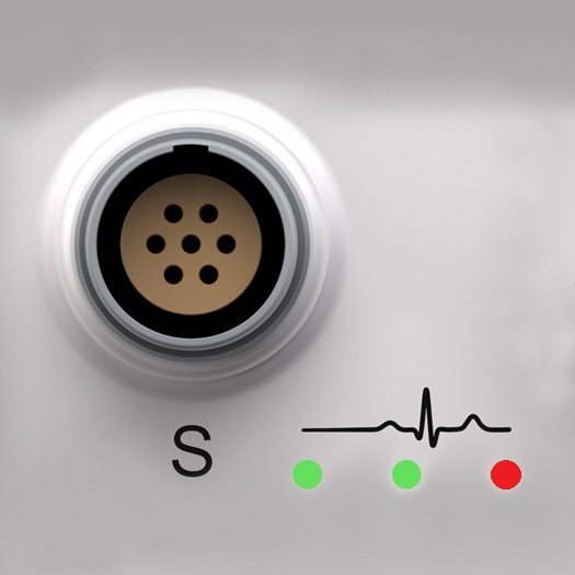
Flashing green LED indicates the MICROQ is the PTP master. Solid green LED indicates the MICROQ is the PTP slave and locked onto the PTP master clock.
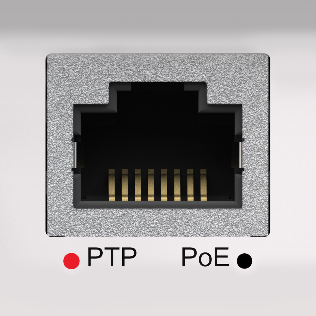
Solid red LED indicates the MICROQ is the PTP slave and not locked onto the PTP master clock.
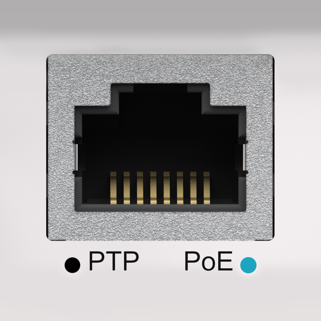
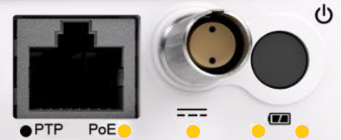
Blue indicates Power over Ethernet is connected and available for use.
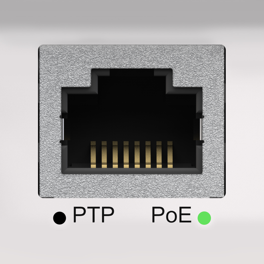
Green indicates Power over Ethernet is connected and active.
Green indicates the MICROQ is being powered using DC Power.
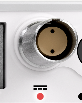
Red indicates there is a problem with the DC Power source. This could indicate either over voltage or a polarity fault of the connected power source.
Note: The DC Power Source LED will only be on if DC Power is being used to power the MICROQ. If the MICROQ is using another power source to operate, the DC Power LED will be off.
The LEDs for the Internal Battery and External Battery are found below the power button. These LEDs indicate the Status and Power Levels of the Batteries.
The Internal Battery LED is found on the left of the two MICROQ Battery LEDs.
The External Battery LED is found on the right of the MICROQ Battery LEDs.
Blue indicates the battery is on standby.
If the blue LED is flashing, that battery is charging. If it is solid blue, that battery is available for use but not yet active.
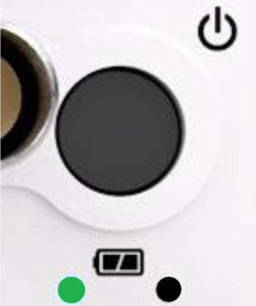
Green indicates the battery is active (currently being used as the main power source). This LED will be off if there is no Internal Battery or if the MICROQ is not switched on.
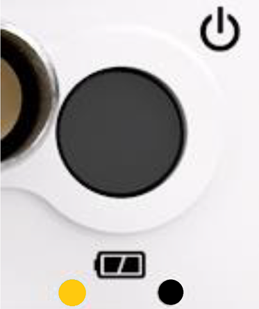
A solid orange light on the Internal Battery LED (left) indicates low Internal Battery power (the battery’s power is below ±27% and there are about 20 minutes of operation time left). When this takes place, the Internal Battery needs to be charged soon or an External Battery needs to be connected soon. If the orange light starts flashing, the battery power is very low (less than ±16%, with about 10 minutes of operation time left) and the Internal Battery needs to be charged immediately or an External Battery needs to be connected immediately.
A solid orange light on the External Battery LED (right) indicates low battery power (the battery’s power is below ±27% and there are about 20 minutes of operation time left). When this takes place, the current External Battery needs to be replaced with a charged External Battery soon. If the orange light starts flashing, the battery power is very low (less than ±16%, with about 10 minutes of operation time left) and the current External Battery needs to be swapped with a charged External Battery immediately.
The Internal Battery will automatically power the MICROQ during External Battery exchanges (hot swapping).
If you have not connected an External MICROQ Battery or the MICROQ is not switched on, the right LED will be off.
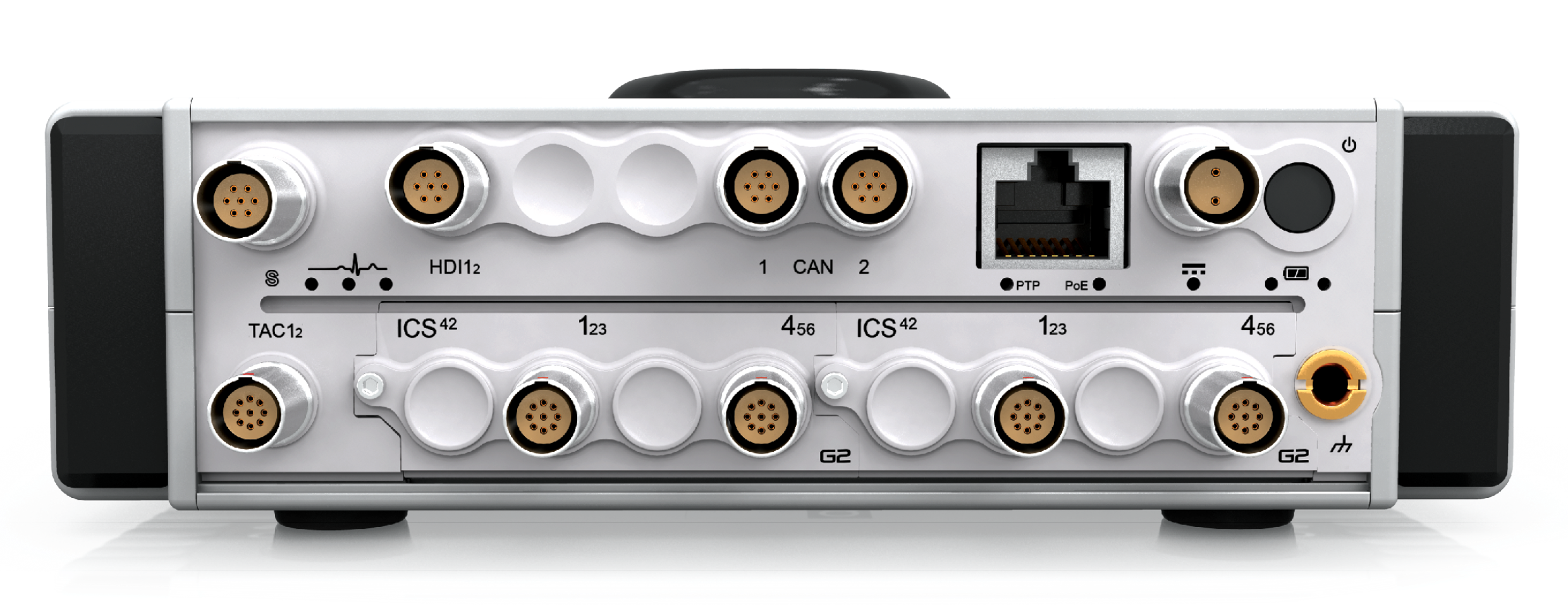
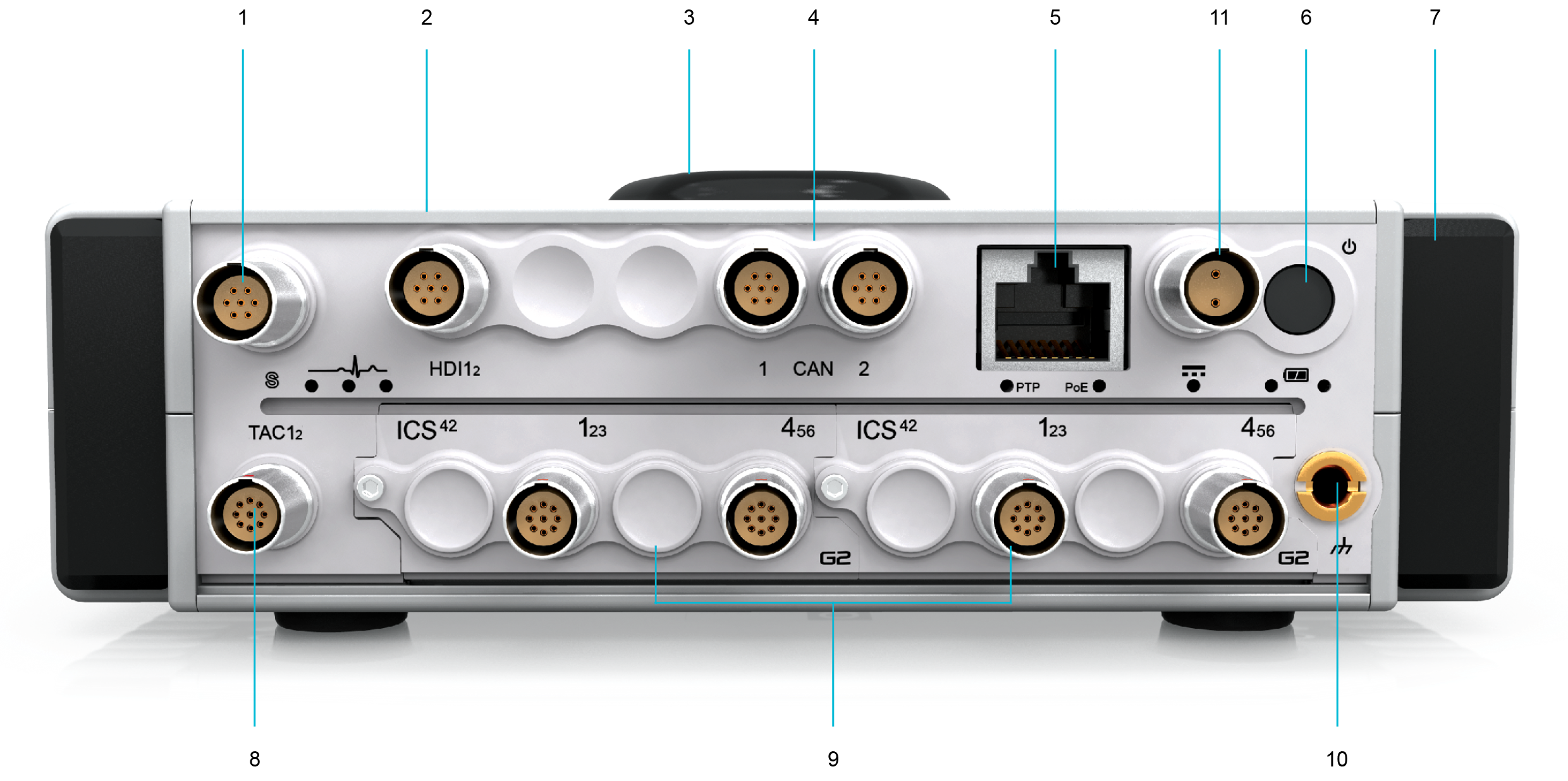
The MICROQ’s front panel supports the following optional built-in Signal Conditioning channels:
The sections below provide general features of each channel.
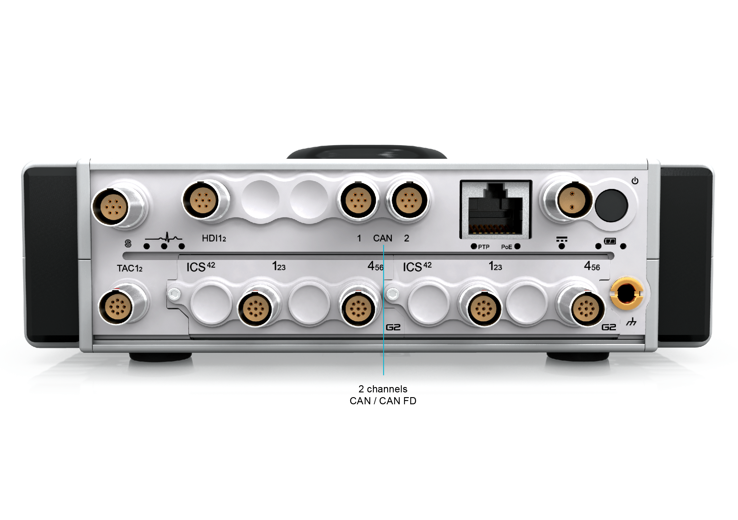
The MICROQ provides an interface to connect to two CAN and CAN FD (CAN with Flexible Data-Rate) busses. CAN FD is an extension of the original CAN (Controller Area Network) protocol, which allows for higher data bandwidth. Received CAN messages are time-stamped to synchronize their reception with analog and digital measurements from other Modules in the system. Features include Participate mode, Listen-Only mode and Loopback mode 1. These channels provide independent CAN message receive filtering for each channel.
The channels can be used:
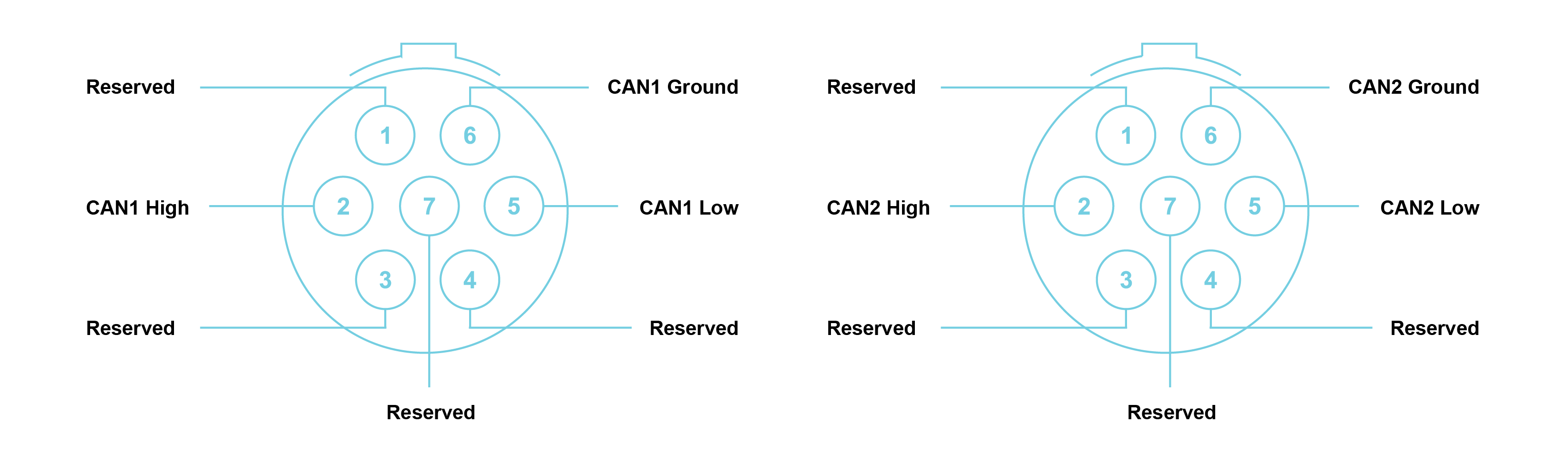
Note: Connectors are shown as if looking into the front panel’s connector or at the rear of the cable’s connector. It is recommended that a FGG.0B.307.CYCD52Z mating connector be used.
.png)
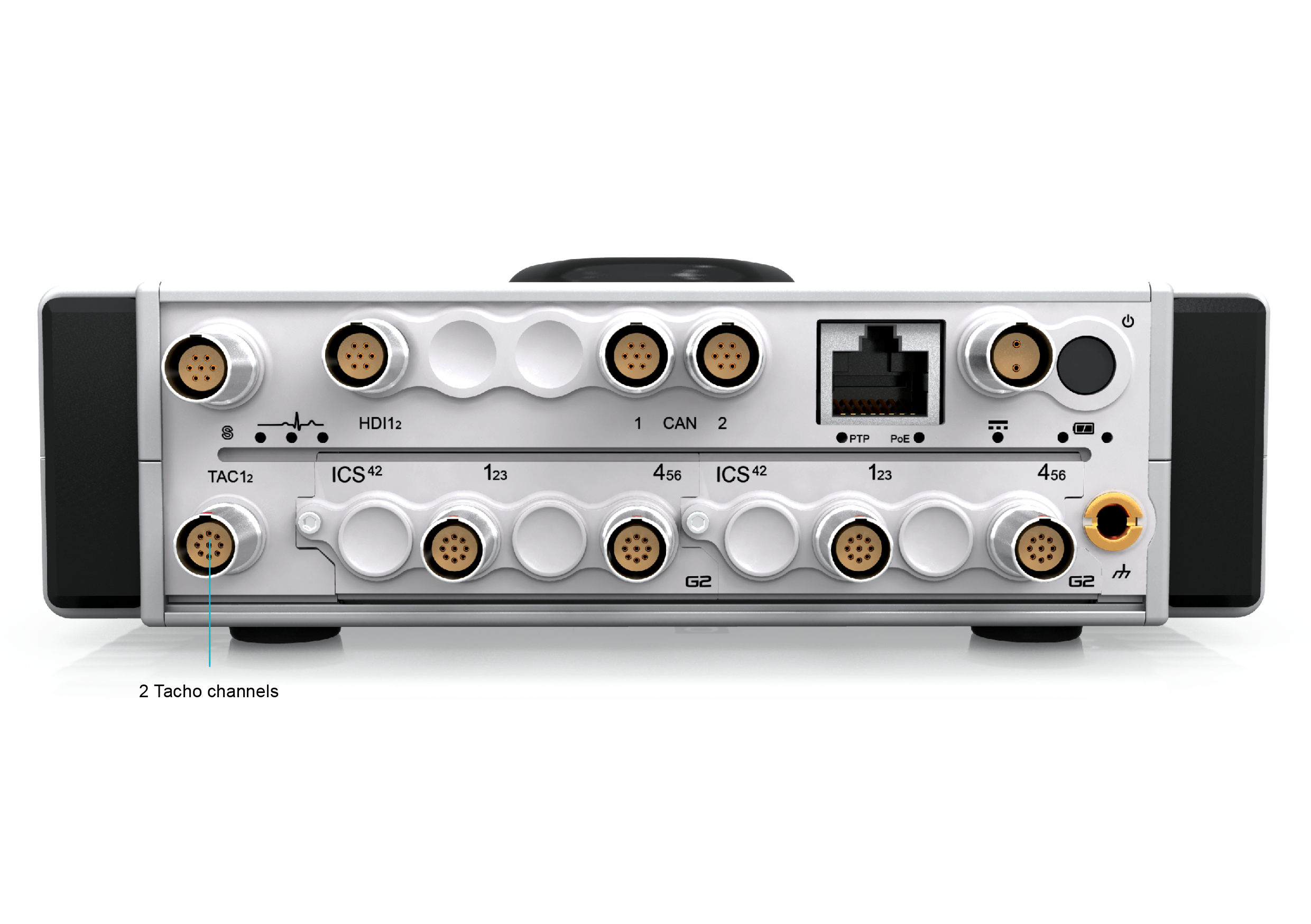
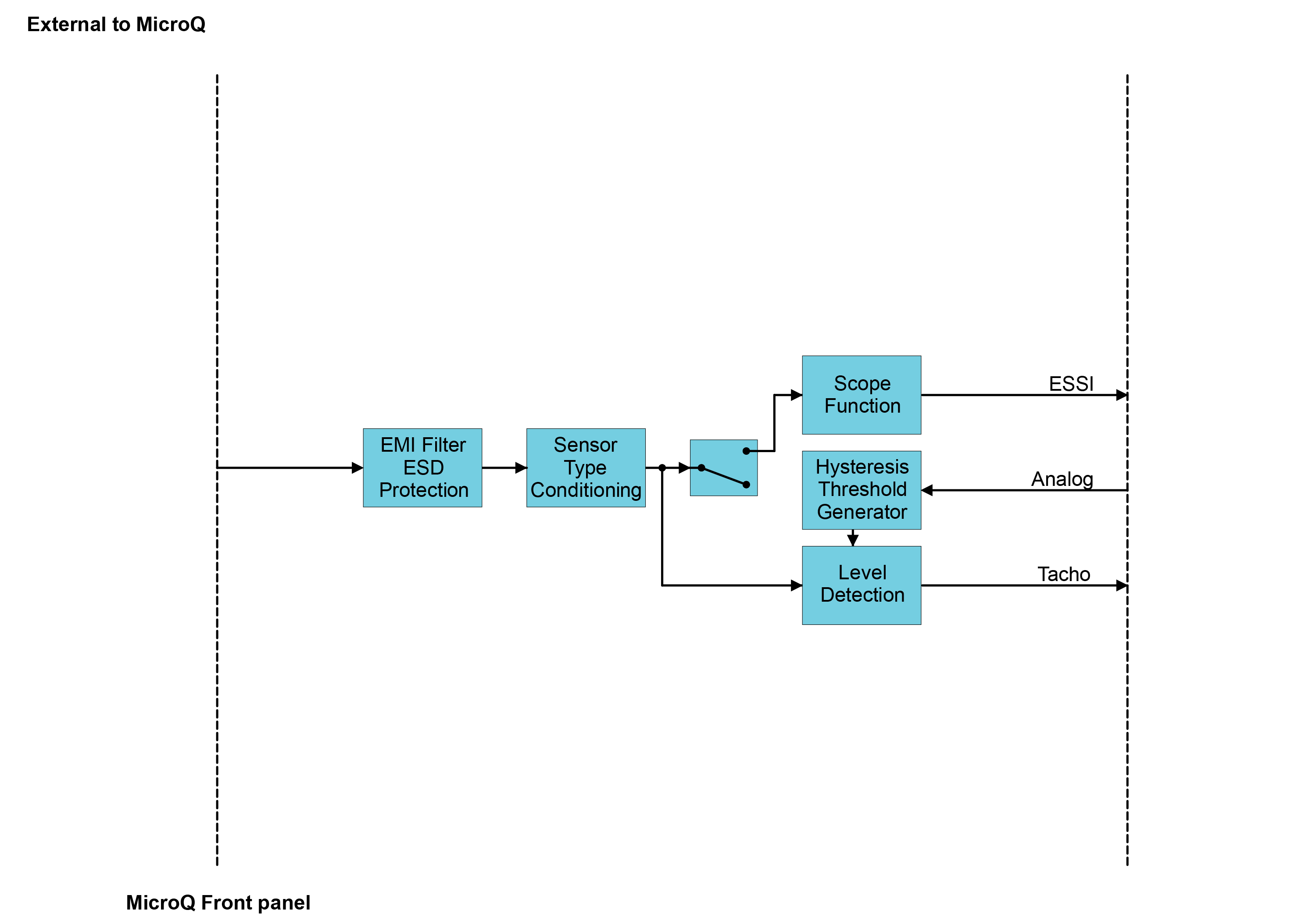
The TAC interface on the front panel of the MICROQ has two Tacho channels which provide time period measurements with a 20 ns resolution, sampled where the signal intersects its trigger level settings. Triggering of Tacho signals can be set for rising or falling edges with adjustable hysteresis, whilst additionally providing AC coupling for sensors with varying DC voltage offsets. A 6.5 MSa/s scope mode is provided per channel to view the Tacho signals in order to assist with the definition of trigger levels. The channels can be used when measuring the pulse rate as well as time between pulses, such as rpm and crank angle.
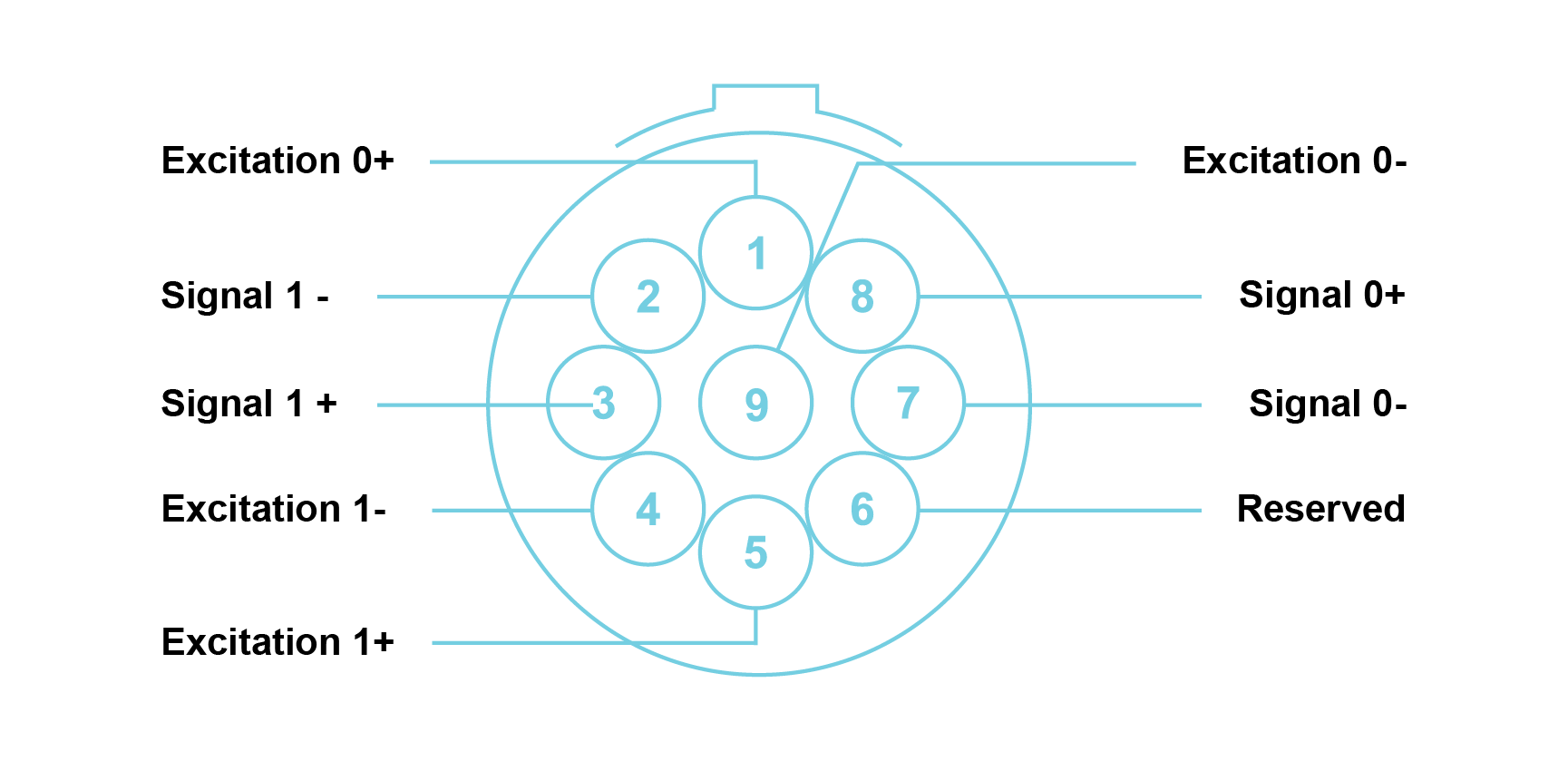
Note: Connectors are shown as if looking into the front panel’s connector or at the rear of the cable’s connector. It is recommended that an FGG.0B.309.CYCD52Z mating connector be used.
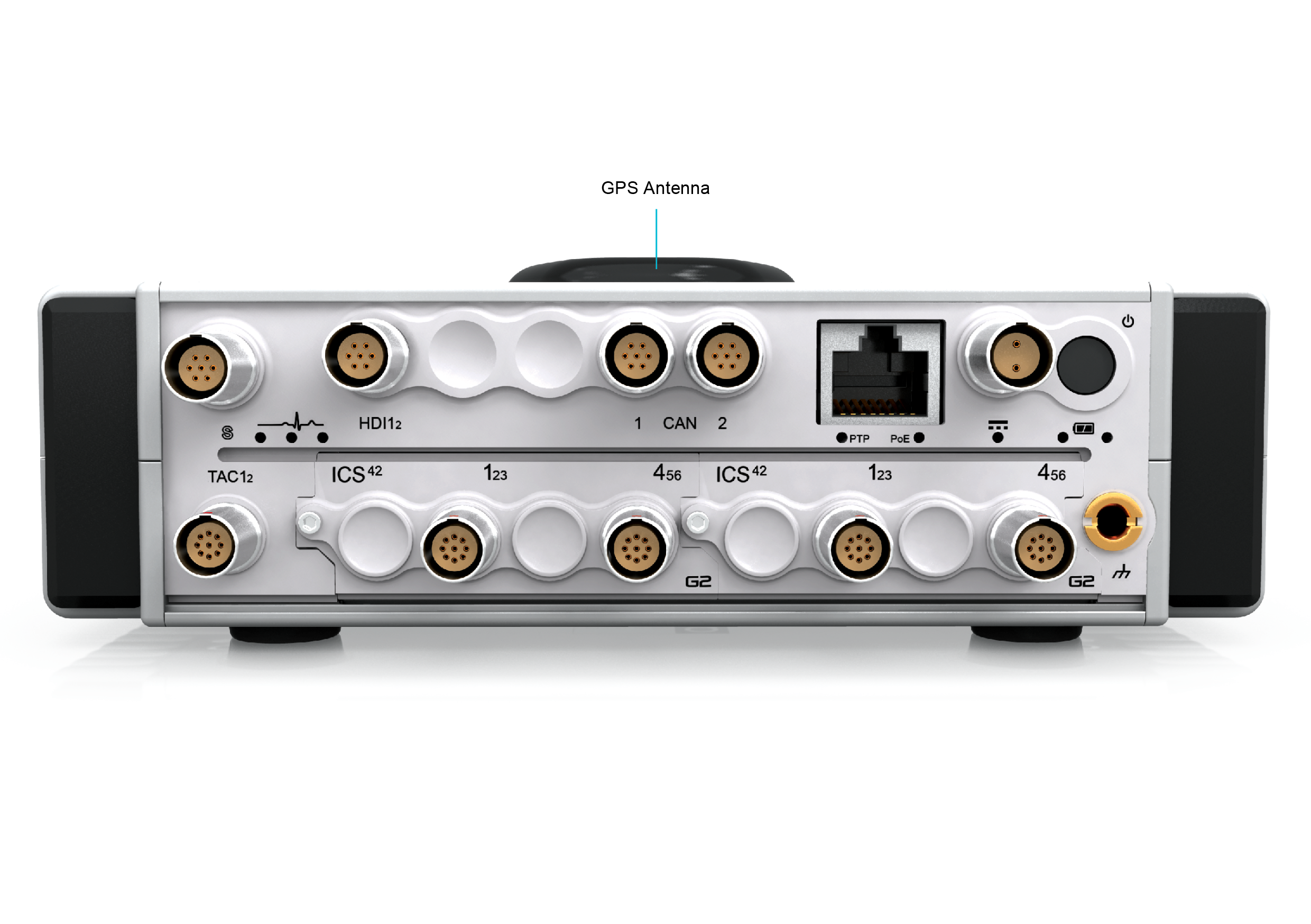
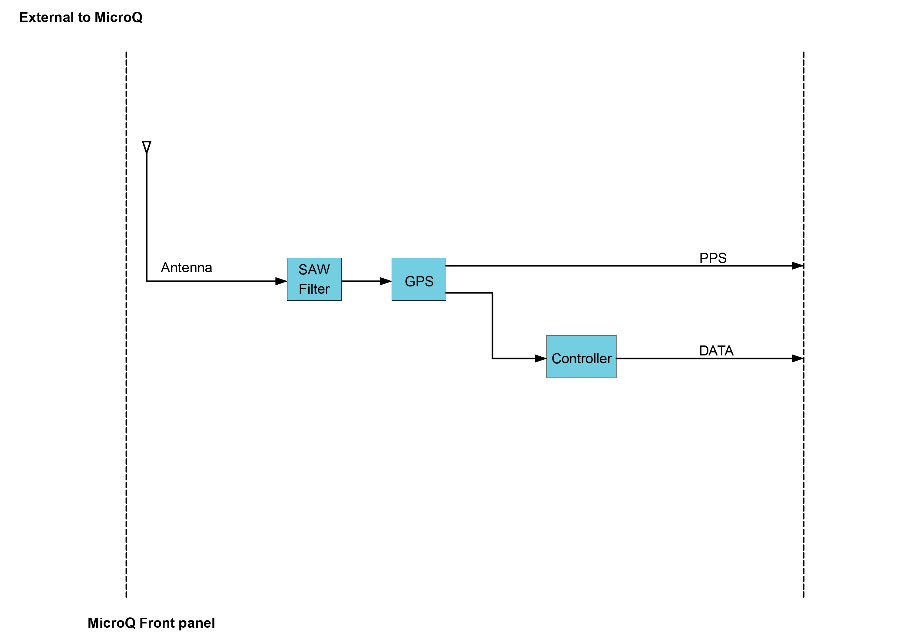
The built-in GPS channel is a professional GNSS receiver and sensitive active antenna, built into the MICROQ’s top antenna housing. It can be used for location logging of measurements, time-of-day synchronization and location or velocity measurement triggering.
The accuracy of the GPS depends on many factors. Typical GPS performance indicators are:
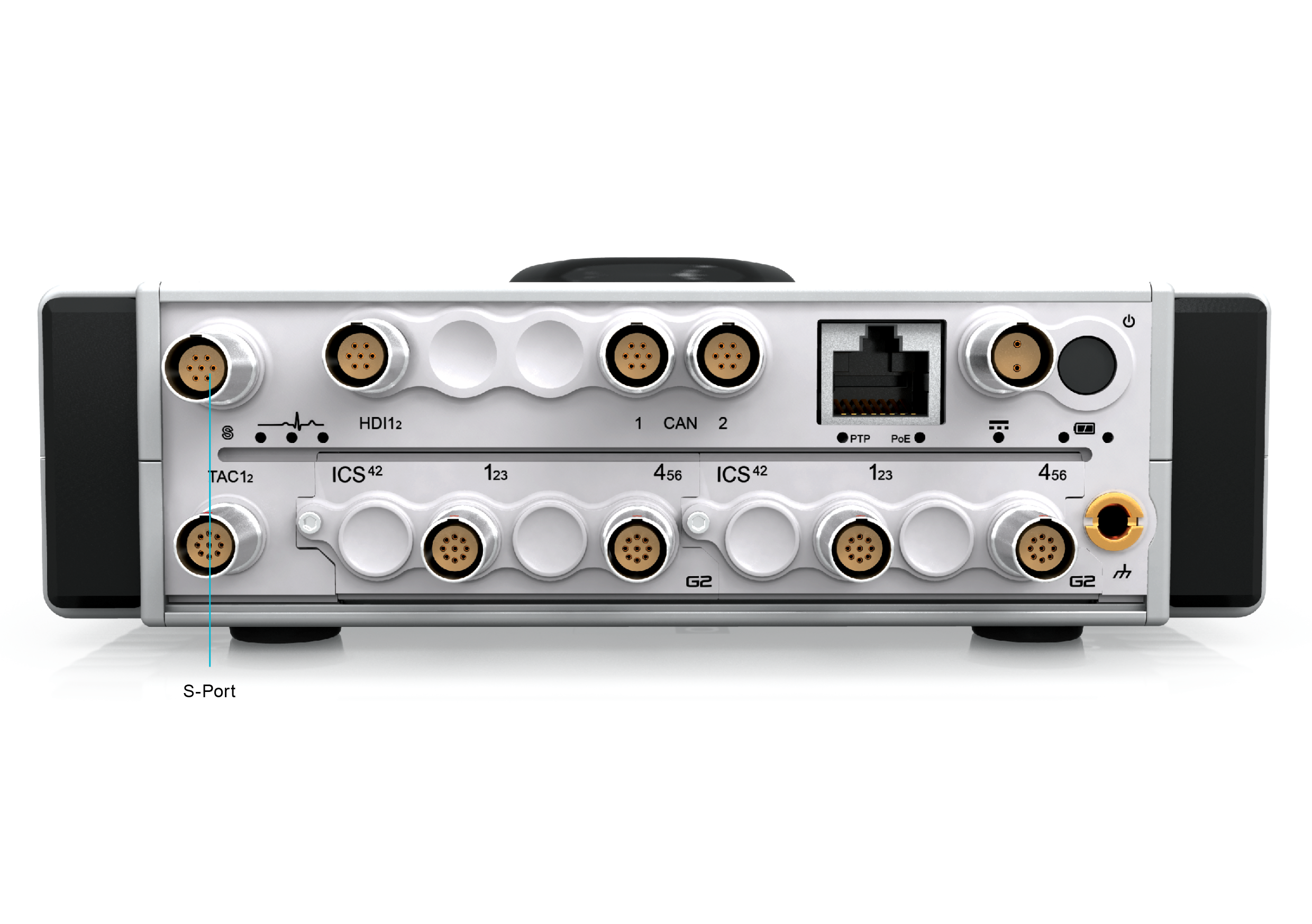
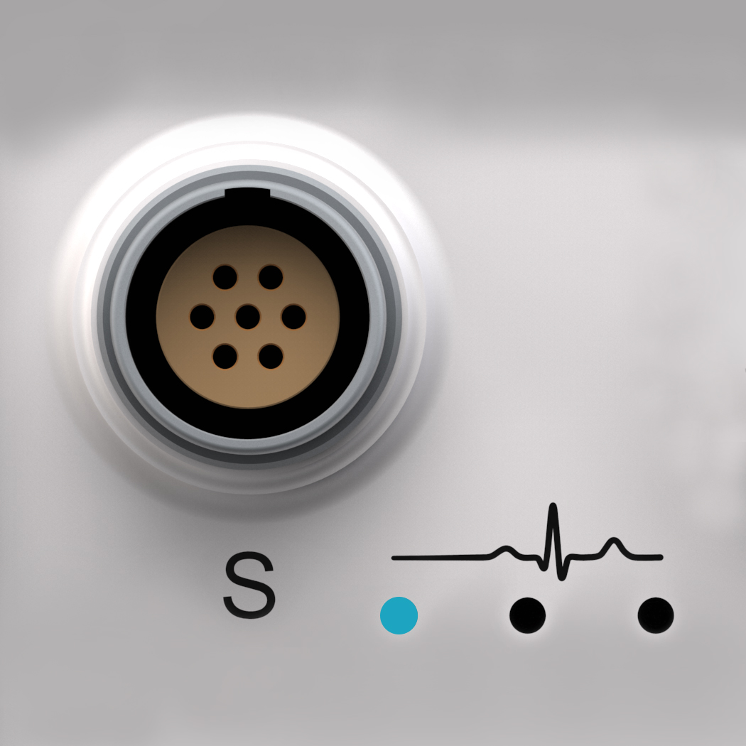
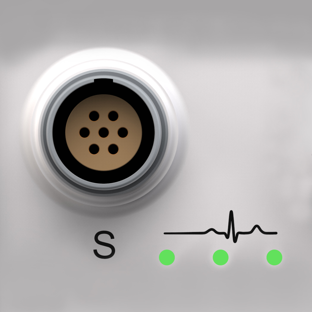
The S-Port is found on the MICROQ’s front panel and can connect to a variety of optional tethered ATTOQs. Examples of these ATTOQs include the NAV and the GPS.
Note: Connectors are shown as if looking into the front panel’s connector or at the rear of the cable’s connector. It is recommended that an FGG.0B.307.CYCD52Z mating connector be used.
Note: The maximum power available from the STP port is: 12 V @ 1 A and 5 V @ 1 A.
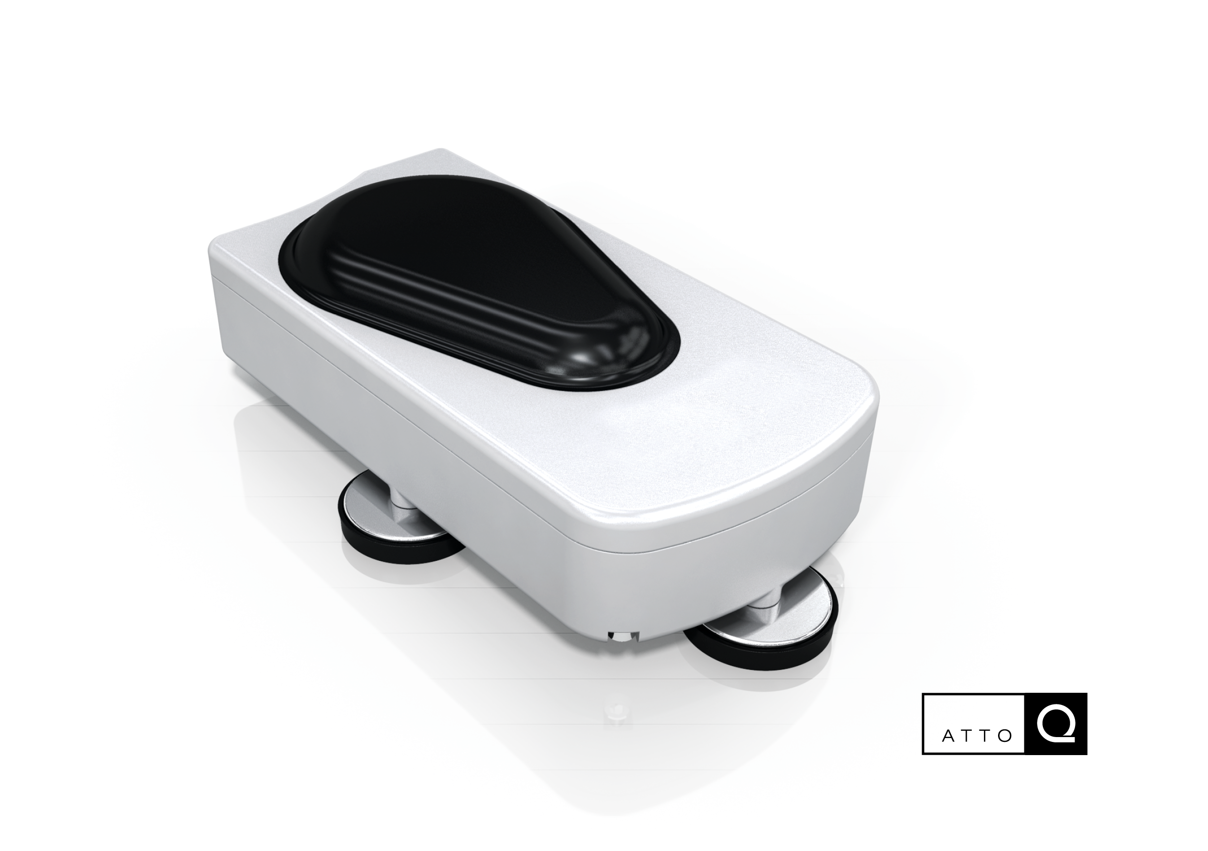
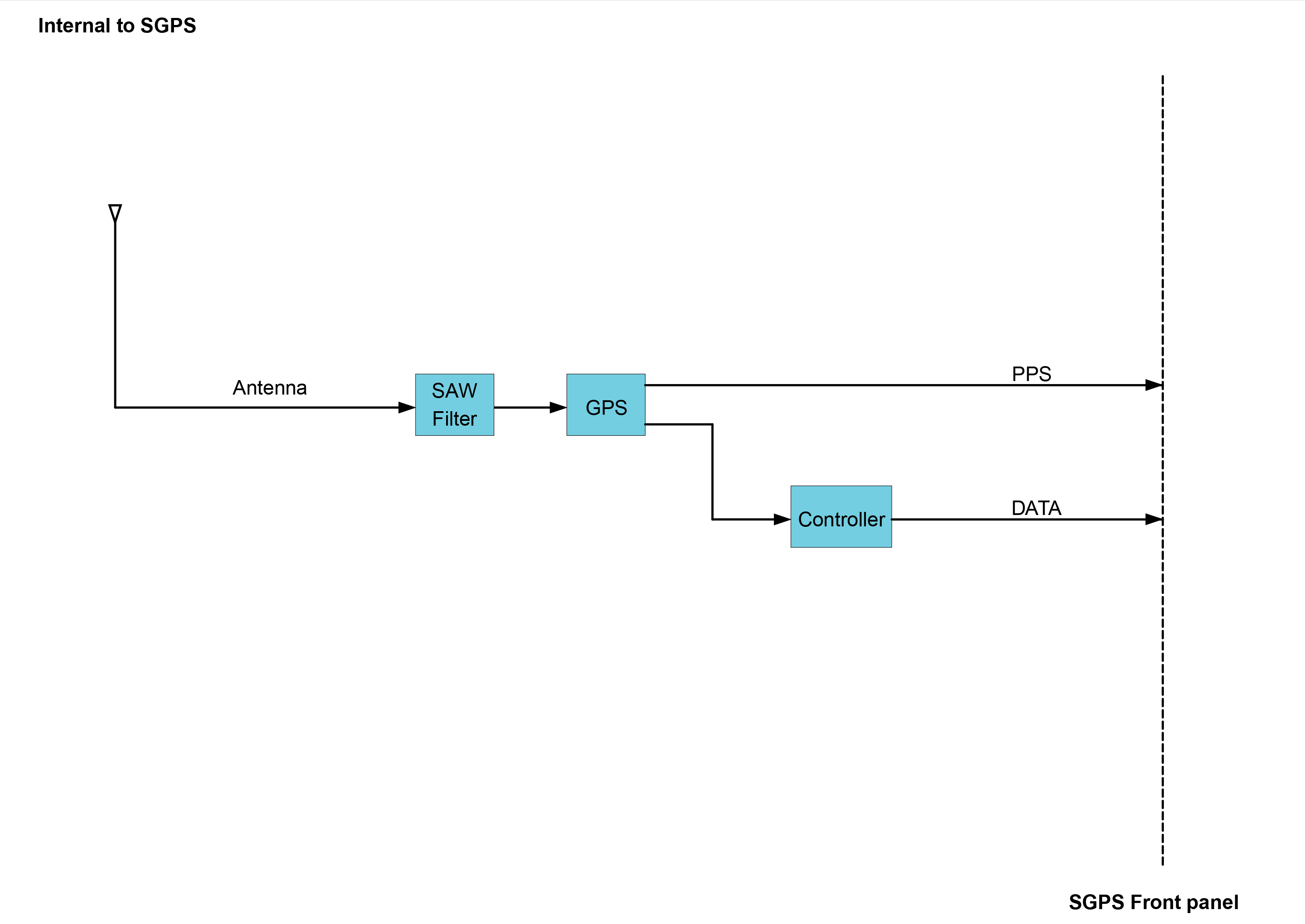
The S-Port increases measurement variety and measurement placement possibilities. There are currently two ATTOQs for S-Port available, the SGPS and the SNAV.
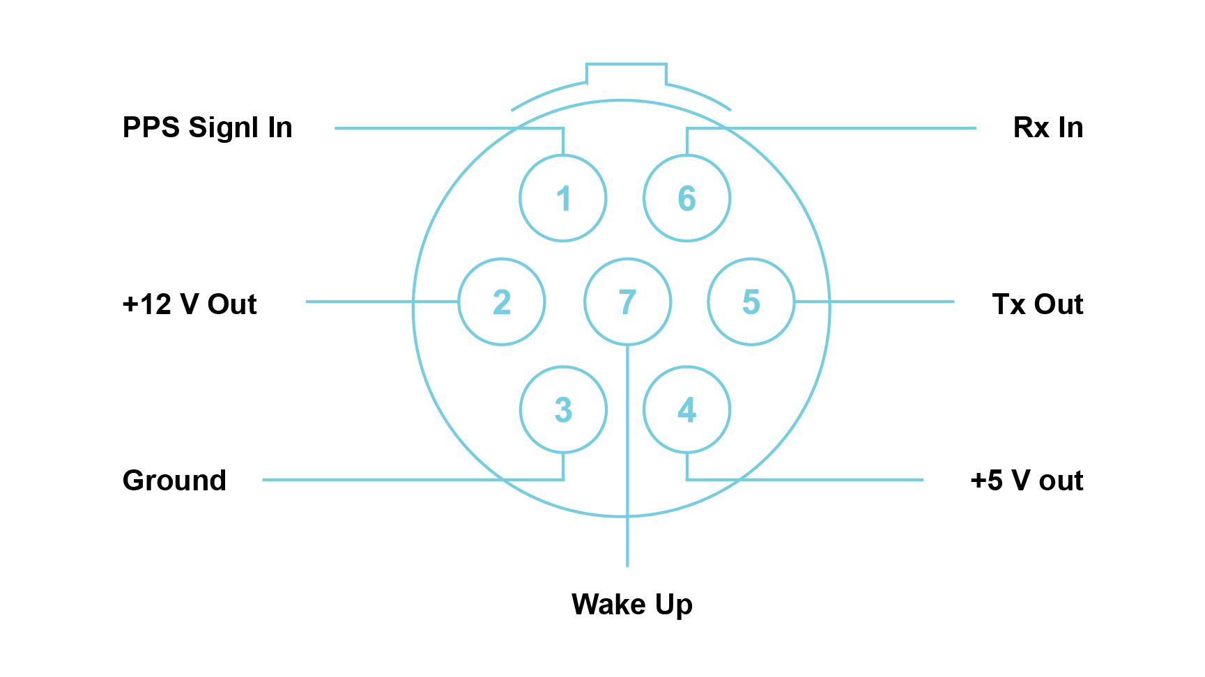
The SGPS facilitates precise time synchronization and position information using a GPS receiver and antenna which can be placed up to 3 m away from the MICROQ.
Note: Connectors are shown as if looking into the front panel’s connector or at the rear of the cable’s connector. It is recommended that an FGG.0B.307.CYCD52Z mating connector be used.
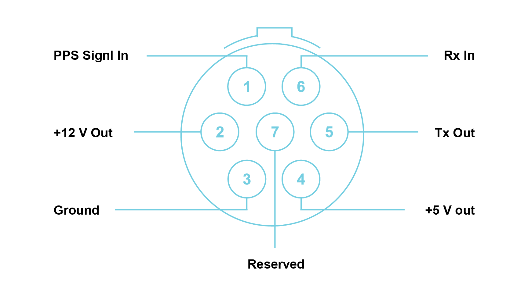
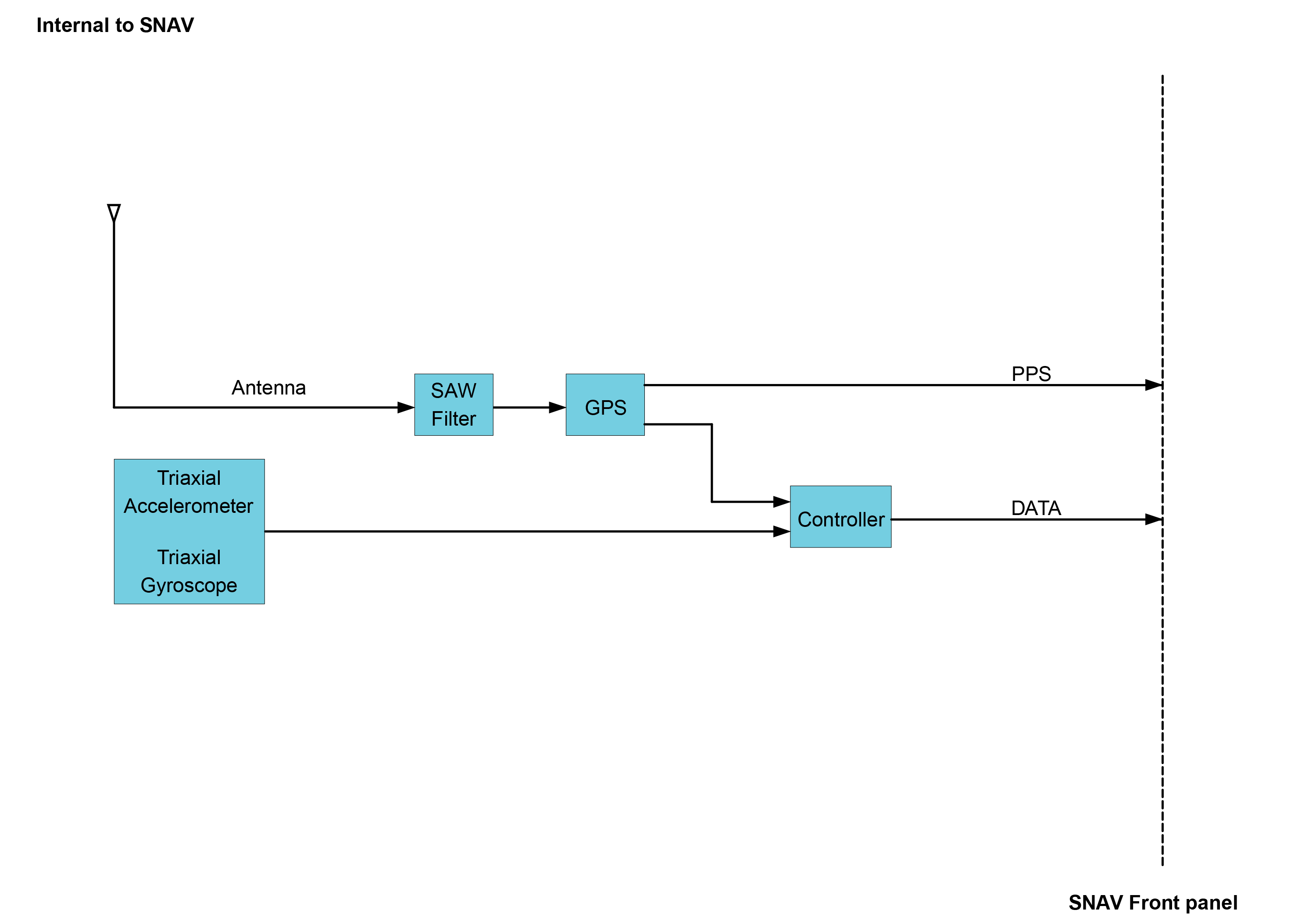
The SNAV is designed to measure the speed of vehicles while driving outdoors. It is suited for Pass-By testing of vehicles to test according to the European standard UNECE 51.03. It is an inertia assisted GPS for high resolution velocity measurement at update rates of up to 100 Hz.
Note: Prescribed Conditions below:
Note: Connectors are shown as if looking into the front panel’s connector or at the rear of the cable’s connector. It is recommended that an FGG.0B.307.CYCD52Z mating connector be used.
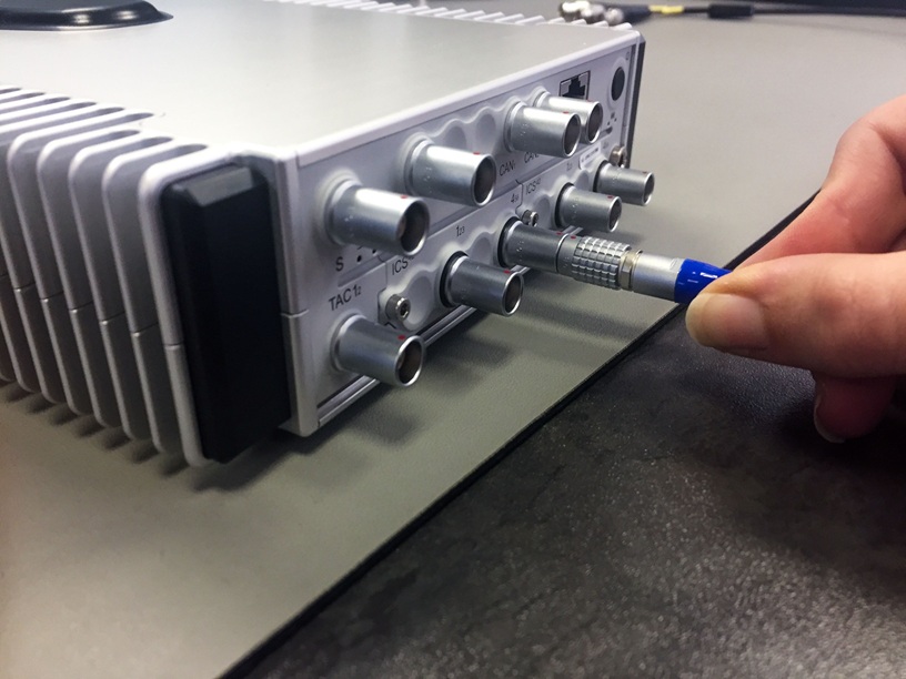
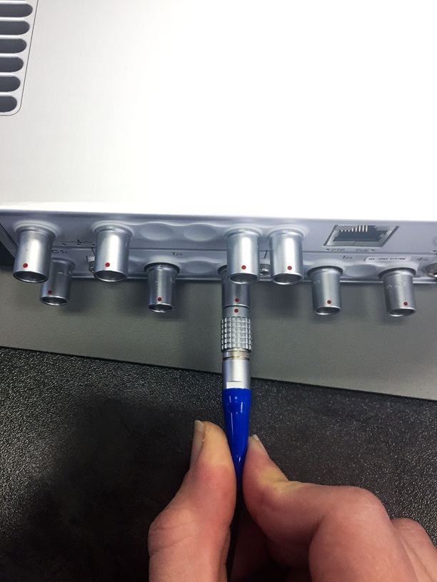
The MICROQ’s S-Port and power connector, as well as most QModules, use LEMO® connectors.
When plugging-in and unplugging LEMO® connectors, please make sure to use the latching sleeve (rough metallic cover) when pulling and pushing in the connector. Do not plug or unplug the LEMO® connectors by pulling on the cable itself. This will damage the cable, affecting measurements.
The following images show how to plug / unplug the LEMO® connector using the latching sleeve provided:
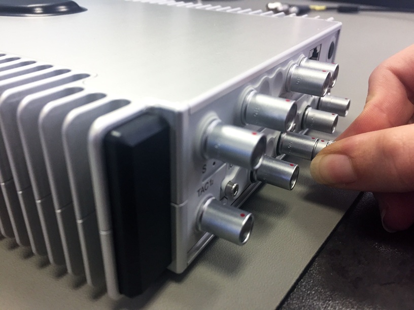
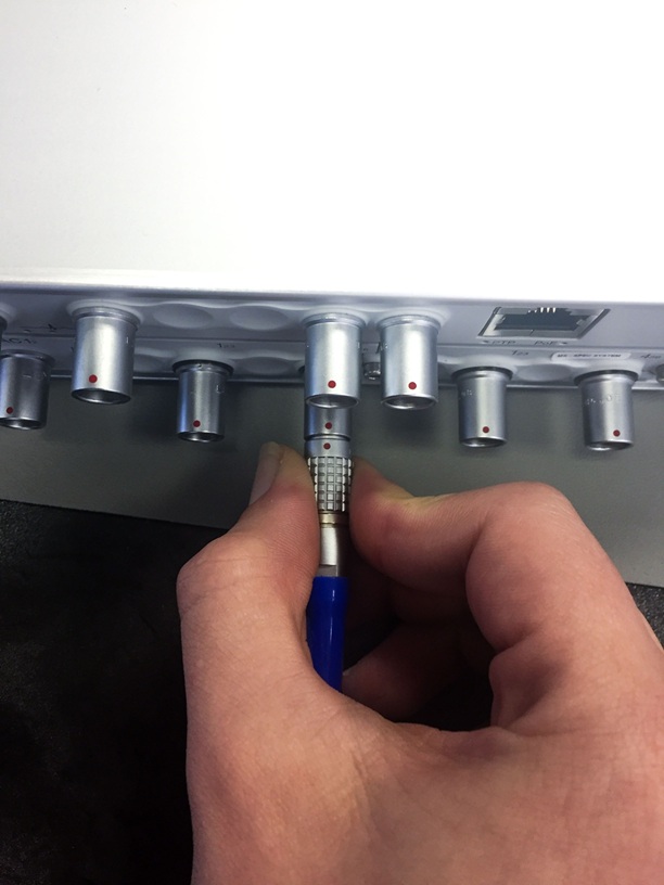
Note: The images below show the incorrect way to plug / unplug the LEMO® connector (by pushing and pulling on a cable). Take care not to do this:
| Product Name | Part Number | Recommended Mating Connector |
|---|---|---|
| CAN42S | LEMO® EHG.0B.307.CLN | 7-pin LEMO® straight plug FGG.0B.307 |
| FLX42 | LEMO® EHG.0B.307.CLN | 7-pin LEMO® straight plug FGG.0B.307 |
| GPS42S | SMA | SMA (Male) |
| Product Name | Part Number | Recommended Mating Connector |
|---|---|---|
| ALO42S | LEMO® EGG.0B.307.CLN | 7-pin LEMO® straight plug FGG.0B.307 |
| CHG42S | 10-32 Microdot jack | Microdot screw-on plug |
| CHS42X | LEMO® EHG.0B.309 CLN | 9-pin LEMO® straight plug FGG.0B.309 |
| DCH42S | Twin-BNC receptacle | Amphenol Twin-BNC clamp plug 31-224 or 31-2226 |
| ICP42 | SMB jack (Radiall R114426000) | 50 Ω Radiall SMB plug |
| ICP42S | LEMO® EHG.0B.303.CLN | 3-pin LEMO® straight plug FGG.0B.303 |
| ICS42 | LEMO® EHG.0B.309.CLN | 9-pin LEMO® straight plug FGG.0B.309 |
| ICT42 | SMB jack (Radiall R114426000) | 50 Ω Radiall SMB plug |
| ICT42S (1) | LEMO® EHG.0B.303.CLN | 3-pin LEMO® straight plug FGG.0B.303 |
| ICT42S (2) | LEMO® EHG.0B.304.CLN | 4-pin LEMO® straight plug FGG.0B.304 |
| MIC42X | LEMO® EGG.1B.307.CLN | 7-pin LEMO® straight plug FGG.1B.307 |
| THM42 | LEMO® EHG.0B.307.CLN | 7-pin LEMO® straight plug FGG.0B.307 |
| WSB42X | LEMO® EGG.0B.307.CLN | 7-pin LEMO® straight plug FGG.0B.307 |
The MICROQ acquires data from its input channels in real-time for subsequent analysis on the data. It offers two methods to synchronize its local clock with an external clock source in order to share a common time base with other systems:
The MICROQ uses Clock Tuning Synchronization instead of Common Clock Synchronization.
A control loop uses PTP timing information (or the GPS synchronized pulse signal) to train the local oscillator in each MICROQ. After a few cycles, the control loop will lock. Once locked, synchronization requires the control loop to continuously train the local oscillator with small increments.
Two parameters are extracted from these timing protocols, namely ‘Absolute Time’ and ‘Relative Time’. These parameters allow MICROQ systems (and other QuantusSeries systems) to be synchronized. The control loop compares ‘Relative Time’ values to corresponding values of the tunable oscillator. Over time, the difference between those values is brought as close to zero as possible.
Precision Time Protocol (PTP IEEE 1588-2008) synchronization achieves clock frequency and phase synchronization between multiple MICROQs on the same network. The IEEE 1588-2008 standard ensures high precision, accuracy and robustness, making it perfect for synchronizing measurement systems.
To synchronize MICROQs using PTP, use the Ethernet interface on the front panel of the MICROQ. Make sure the Ethernet switch is PTP-aware and an external PTP Master Clock is being used. PTP synchronization connects all MICROQs to a single network with Ethernet as the communication medium. The PTP Master Clock is identified using the best master algorithm, whereafter all other clocks synchronize directly to the master clock.
Any number of MICROQs can form part of the same system using PTP synchronization. The only criterion is that each MICROQ be connected to the same PTP-enabled network via its Ethernet interface. Network congestion and availability of Ethernet connections dictate the number of MICROQs that can form part of a synchronized Cluster. PTP synchronization is best suited when MICROQs need to be synchronized no more than 100 m apart from each other.
Advantages of PTP synchronization:
Note: Changes in the temperature of a QuantusSeries instrument will affect PTP accuracy.
The User can expect a linear relationship between temperature change and the accuracy. For every C°/minute change in temperature the accuracy deteriorates by about 50 ns.
PTP synchronization will not be supported in combination with the following sampling rates and their derivatives (convertible through factor 2):
Note: These features and specifications may not be included based on the software package utilized with the MICROQ
In a GPS synchronized system, each MICROQ synchronizes using the MICROQ’s built-in GPS or an NAV/GPS. The built-in GPS or GPS/NAV provides timing parameters to train the local clock to compensate for drift. The GPS’s set of satellites send the common synchronized pulse signal, as well as time and position data, to the MICROQ. Once the internal clock has been aligned to the synchronized pulse signal, it is continuously monitored and adjusted to maintain lock.
Note that the process of achieving GPS signal lock and training a local clock to the synchronized pulse signal takes some time. It can take up to two minutes (or longer), depending on environmental factors.
Advantages of GPS synchronization:
Internal GPS features:
If the system is not responding, you can perform a “hard reset” (force a system reset). Press the Power On / Off button down for about 8 seconds. The PoE and Battery LEDs will go from their current states to solid red, solid orange and finally flashing orange. After this, the MICROQ will reset and the LEDs will revert back to their respective initialization indicators.
Note: The MICROQ can only be reset if it is already running.
In order to reset the MICROQ to its default settings, keep the Power On / Off button pressed down for about 3 seconds until the PoE and Battery LEDs turn solid orange, then release the power button. After the button has been released, the PoE and Battery LEDs will return to their original indicator states. Repeat this action three times within 15 seconds. If the reset to default settings is successful, the LEDs will slowly flash orange after the third sequence. The reset settings will be available once the MICROQ has been initialized.
The following LED indicators denote faults / errors related to the MICROQ’s System Status, Application Status and Power over Ethernet. >Note: contact your supplier Partner if your MICROQ displays any of the following:
A Controller Firmware Upgrade is taking place when the PoE status LED as well as both the Battery status LEDs are toggling between blue and purple. Wait until the LEDs have stopped indicating this status. Once the LEDs revert back to their original indicator states, the update has taken place and you can continue to use your MICROQ. These indications are only applicable when a Firmware Upgrade is necessary. For more information regarding Controller Firmware Upgrades, contact your supplier.
A Power Supply Firmware Upgrade is taking place when the PoE status LED as well as both the Battery status LEDs are solid orange. Wait until the LEDs have stopped indicating this status. Once the LEDs revert back to their original indicator states, the update has taken place and you can continue to use your MICROQ.
These indications are only applicable when a Firmware Upgrade is necessary. For more information regarding Power Supply Firmware Upgrades, contact your supplier.
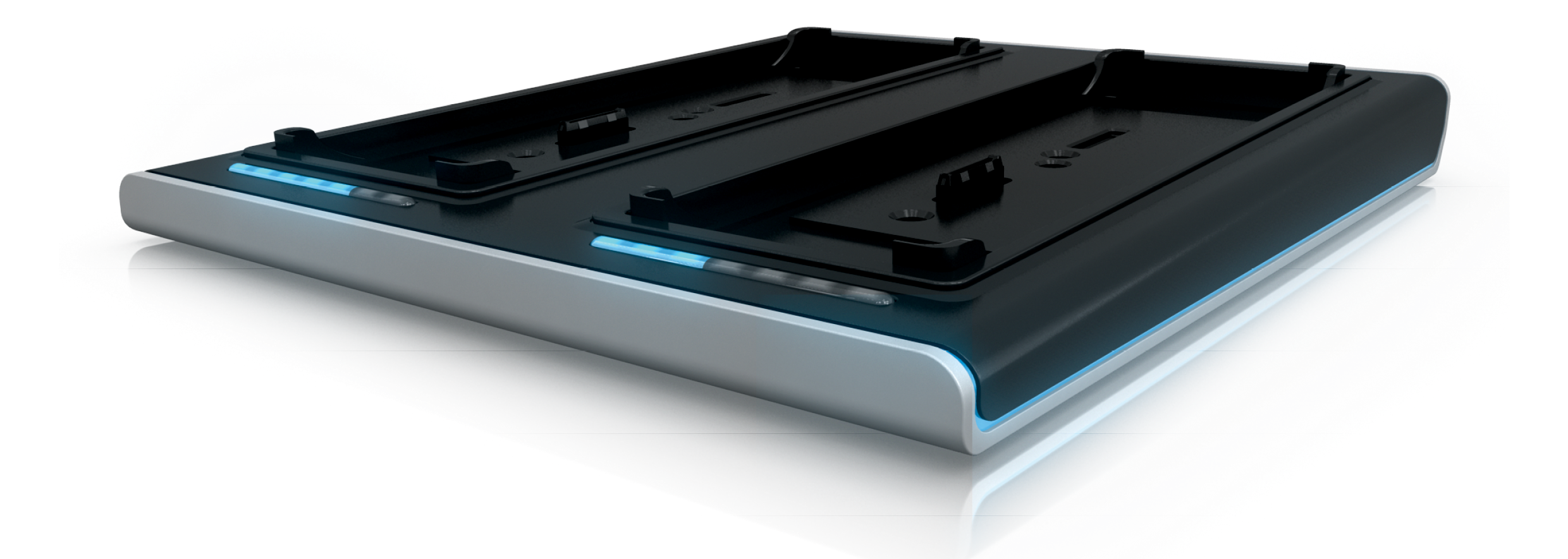
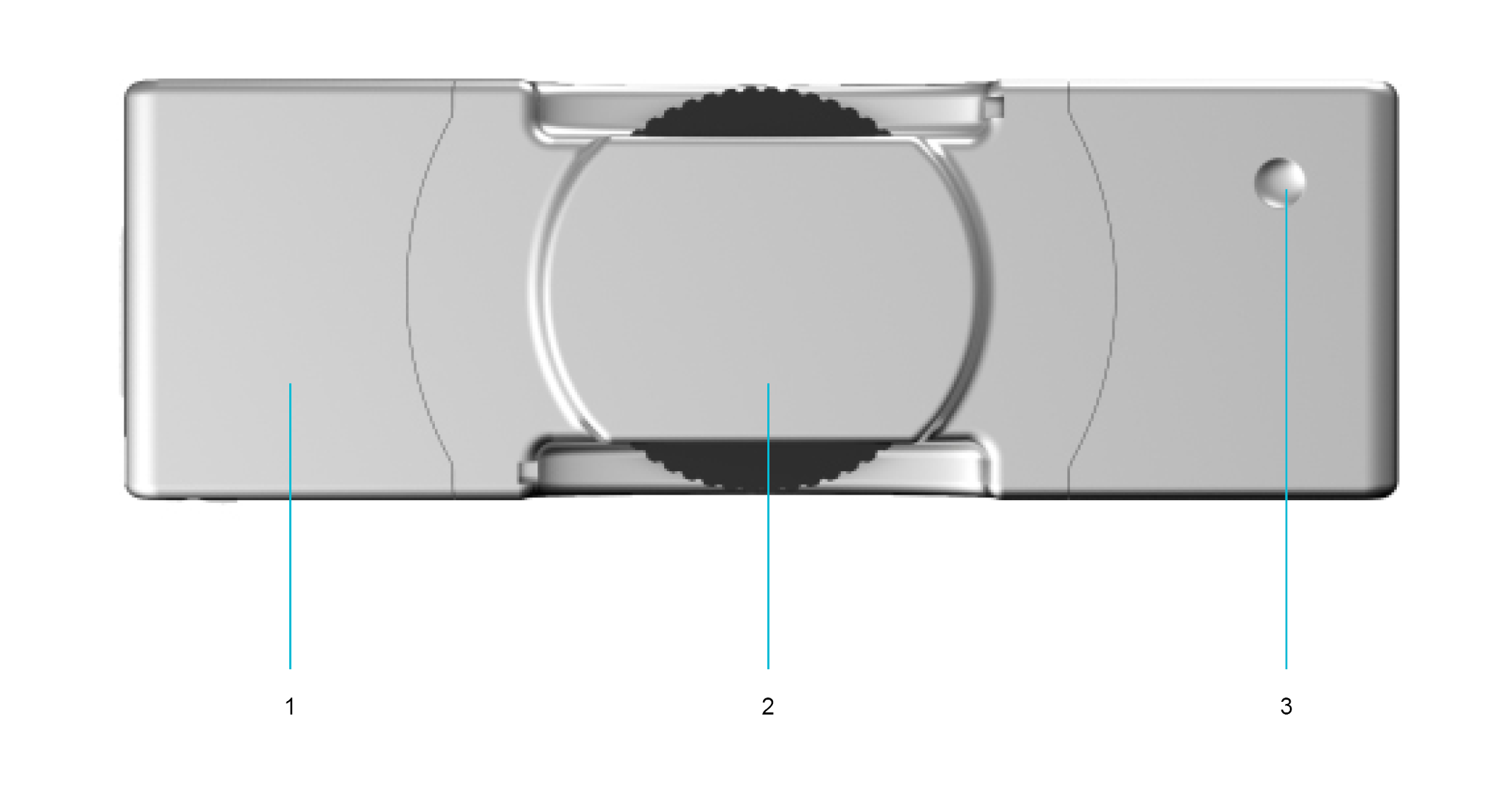
Use the DOCKQ to charge your External MICROQ Batteries, as well as share data on your network.
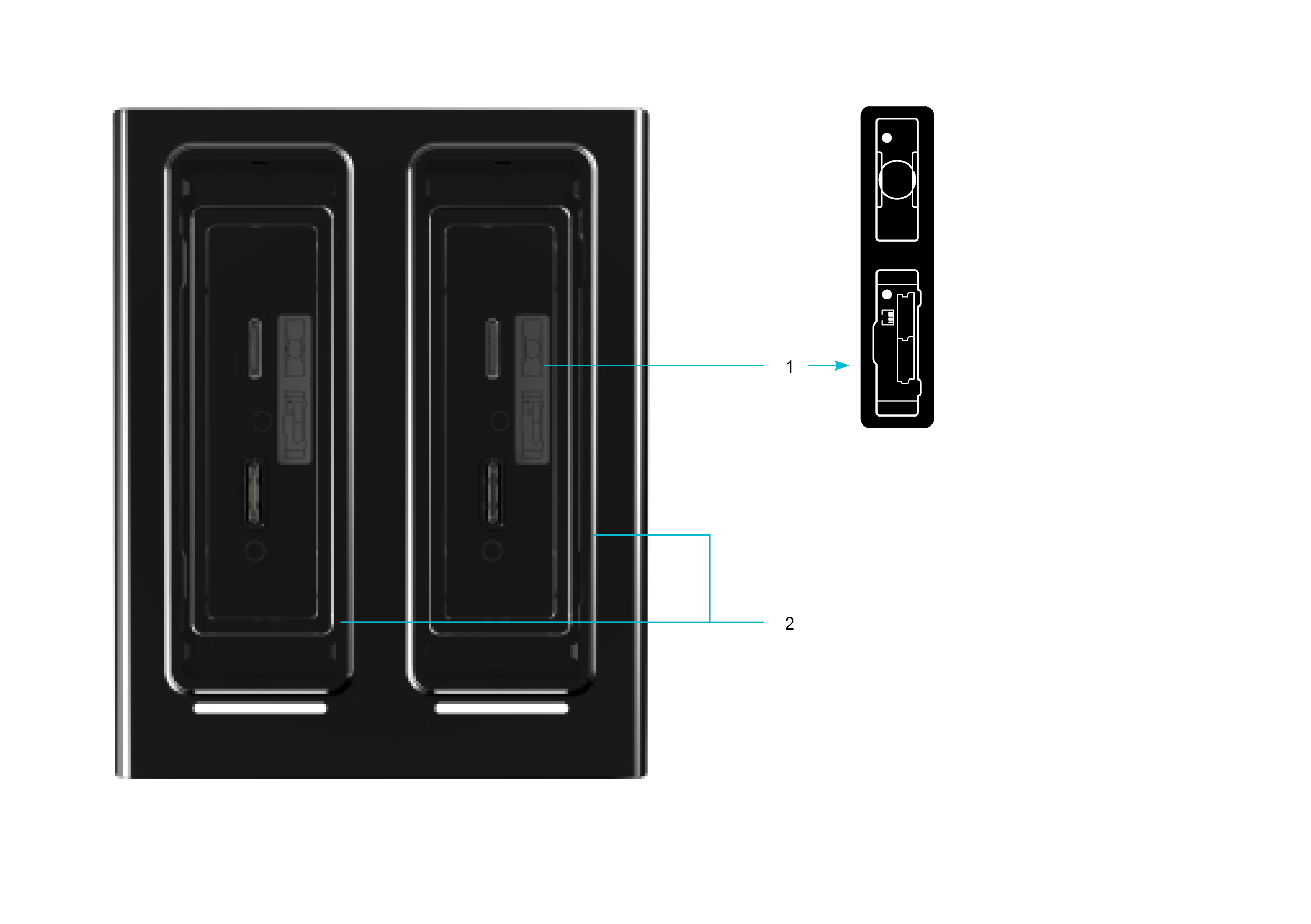
Docking Label
The docking label indicates how to correctly align the connectors on the MICROQ / External Battery with the connectors ofthe DOCKQ bays. The white dots indicate the Indent on the External Battery and the Power On / Off button on theMICROQ. When docking your MICROQ / External Batteries, first consult this label to ensure that the MICROQ / ExternalBattery connectors are properly aligned with the connectors on the DOCKQ bays.
MICROQ Maintenance Bays / External MICROQ Battery Charging Bays
Any of the two DOCKQ bays can act as both MICROQ Maintenance Bays and External MICROQ Battery Charging Bays.
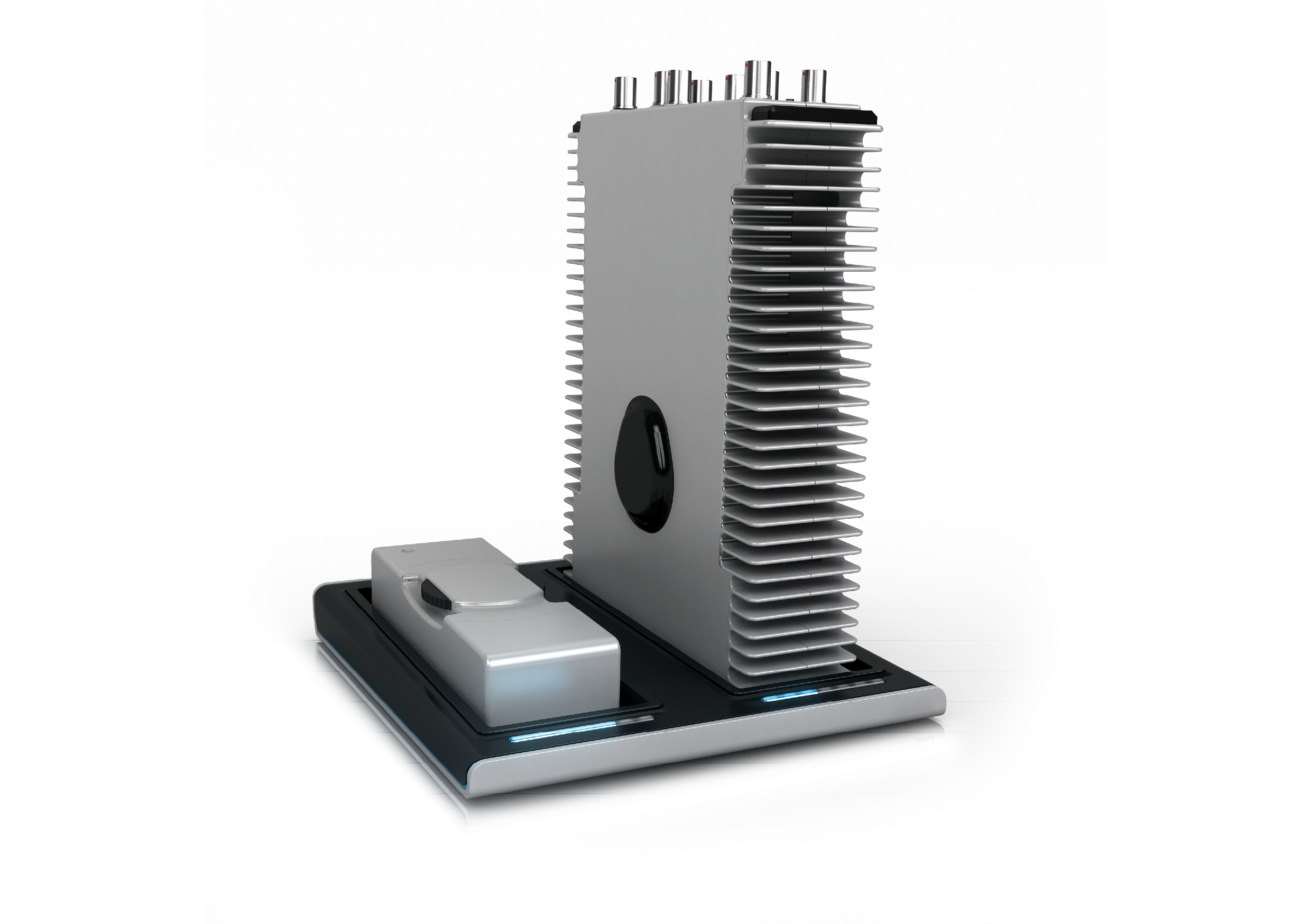
Dock your MICROQ into either one of the MICROQ Maintenance Bays to charge your Internal Battery and connect to your network to share data. Make sure the MICROQ is aligned correctly (see Docking Label). Additionally, make sure your DOCKQ is connected to the network.
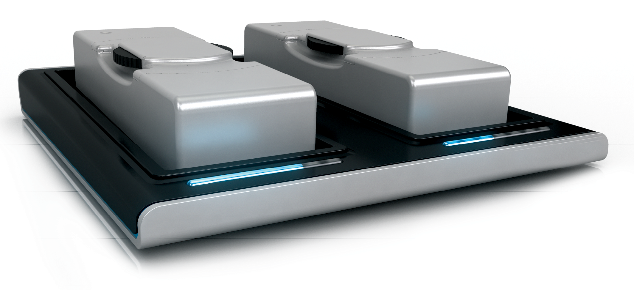
To charge External Batteries, dock them into either one of the External MICROQ Battery Charging Bays. Make sure you align the connectors on the External Battery with the connectors in the Charging Bays according to indications on the Docking Label (see Docking Label).
Note: The temperature range of the batteries needs to be between 0 °C and 45 °C to charge.
The images above show the Top View of the DS20. Information for the DS20 and the DS10 will be the same for this section.
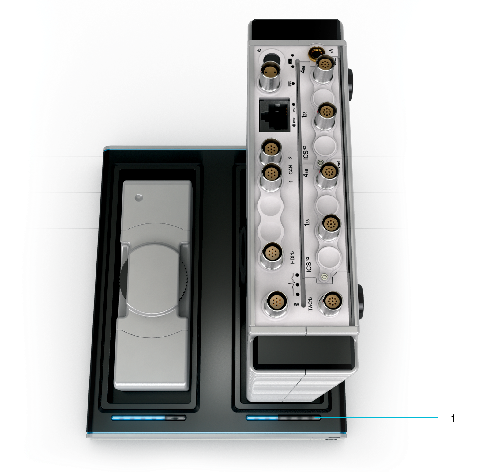
The seven LEDs below each MICROQ Maintenance Bay / External MICROQ Battery Charging Bay indicate the progression of the charge level from the moment the battery is docked, to the moment the battery is fully charged. Once the battery is fully charged, all seven LEDs will be solid blue.
Note: This does not mean the MICROQ or External Battery cannot be used before it is fully charged.
Orange LEDs on the DOCKQ indicate a warning.
If a single orange LED is running over the blue LEDs, the DOCKQ is downloading data from the docked MICROQ. This process should not be interrupted – do not undock the MICROQ while this is taking place.
| Specification | DS10 | DS20 |
|---|---|---|
| Maximum Dimensions (W x L x H) |
183 x 227 x 44 mm (7.2 x 8.94 x 1.73 “) |
183 x 245 x 86 mm (7.2 x 9.65 x 3.39 “) |
| Weight | 1.2 kg (2.65 lbs) |
1.6 kg (3.53 lbs) |
| Operating Humidity | 5% - 90 % RH | 5% - 90 % RH |
| Operating Temperatures | 0 °C to 60 °C | 0 °C to 60 °C |
| Ingress Protection Rating | IP40 | IP40 |
| Typical Mounting | Table top | Table top |
Use your External MICROQ Battery to extend uninterrupted operation time by hot swapping your batteries while conducting your measurements.
Warnings, Certifications, Serial Number and Mecalc’s
Recycling Policy
Note: Be aware of warnings related to the use of the External MICROQ Battery, as well as Mecalc’s battery recycling policy.
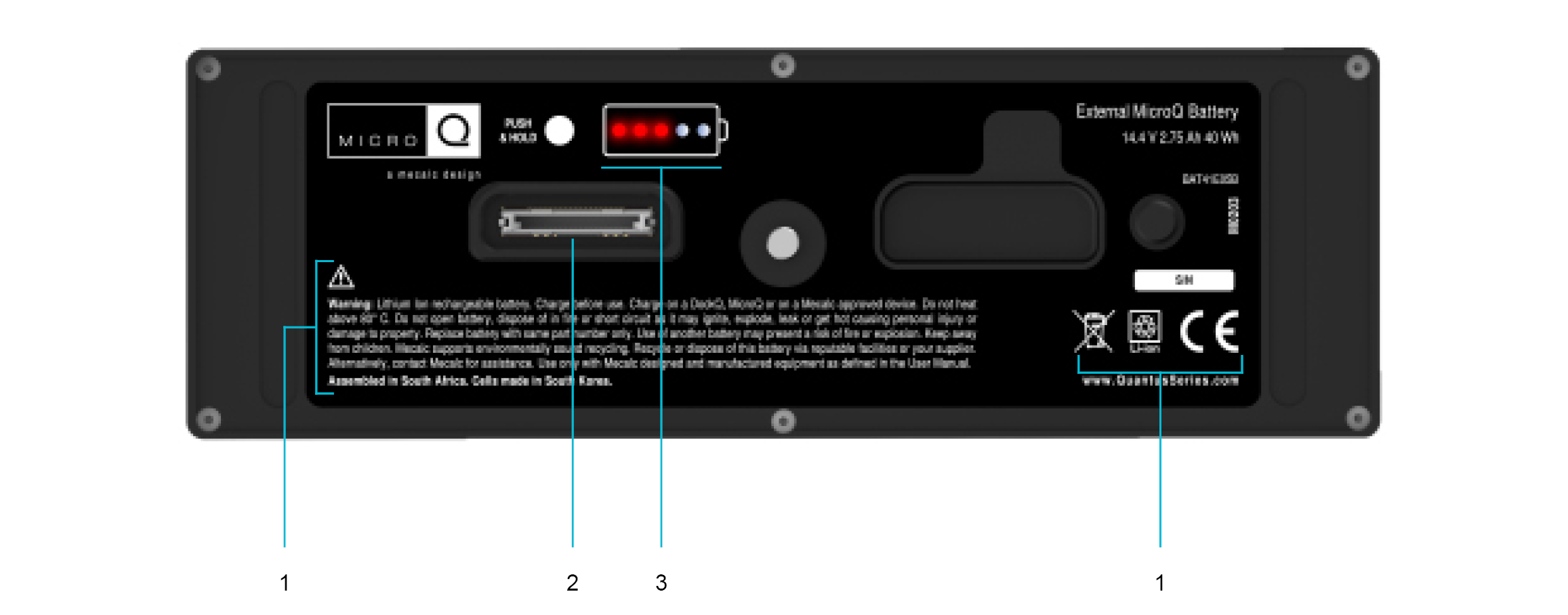
The following warning can be found underneath the General Warning Label on the External MICROQ Battery:
Lithium Ion rechargeable battery. Charge before use. Charge on a DOCKQ, MICROQ or on a Mecalc approved device. Do not heat above 80 °C. Do not open battery, dispose of in fire or short circuit it as it may ignite, explode, leak or get hot causing personal injury or damage to property. Replace battery with same part number only. Use of another battery may present a risk of fire or explosion. Keep away from children. Mecalc supports environmentally sound recycling. Recycle or dispose of this battery via reputable facilities or your supplier. Alternatively, contact Mecalc for assistance. Use only with Mecalc designed and manufactured equipment as defined in the User Guide.
The serial number of the battery can be found above the warning symbols on the front view of the battery.
Note: If, for whatever reason, the serial number is not readable, it should be considered potentially dangerous. Refrain from using the battery and store it in a safe space. Contact your supplier as soon as you are aware of the problem.
MICROQ / DOCKQ Connector
Attaching the
External Battery for more information about how to attach your External
Battery to the MICROQ,and 1.1. Top View for information
about how to dock your External Battery into the
DOCKQ.
Battery Power Level Indicator
To check the
power level of your External Battery, press and hold the white button to
the left of the battery icon until atleast one red LED comes on. The
battery icon’s red LEDs will light up to indicate the battery’s current
power level. Thenumber of LEDs (up to 5) that light up will indicate the
battery’s power level (i.e. one light indicates 20% power; if all
theLEDs light up, the battery is fully charged, i.e. 100%
power).
| Type | Li-Ion |
|---|---|
| Capacity | 40 Wh Battery power for 1 – 2 hours (depending on system configuration) |
| Number of Cells | 4 |
| Mass of each Cell | 48 g |
| Dimensions (W x L x H) | 47 x 145 x 38 mm (1.9 x 5.7 x 1.5 “) |
| Maximum Weight | 0.45 kg (1 lbs) |
| Nominal Voltage | 14.4 V |
| Temperature Range (charging) | 0 °C to 45 °C |
| Temperature Range (discharging) | -20 °C to 60 °C |
Note: Both the Internal and External MICROQ batteries are certified and proved to meet the requirements of each applicable test in the UN Manual of Tests and Criteria, Part III, Sub-Section 38.3 [ST/SG/AC.10/11/Rev.5].
| Overview | An overview of SubModules providing enhanced functionality to corresponding QModules can be found below: |
|---|---|
| TBNC10 | The Tri-BNC10 SubModule is used to split signals from a 9-way LEMO® FGG.0B connector to a single triangular prism with 3 BNC connectors |
| TBNC30 | The Tri-BNC30 SubModule is used to split signals from a 9-way LEMO® FGG.0B connector to 3 single BNC Jack connectors to easily connect sensors |
| TBNC40 | The Tri-BNC40 SubModule is used to split signals from a 9-way LEMO® FGG.0B connector to 3 single BNC Plug connectors to easily connect sensors |
| TSMB10 | The Tri-SMB SubModule is used to split signals from a 9-way LEMO® connector to 3 SMB connectors |
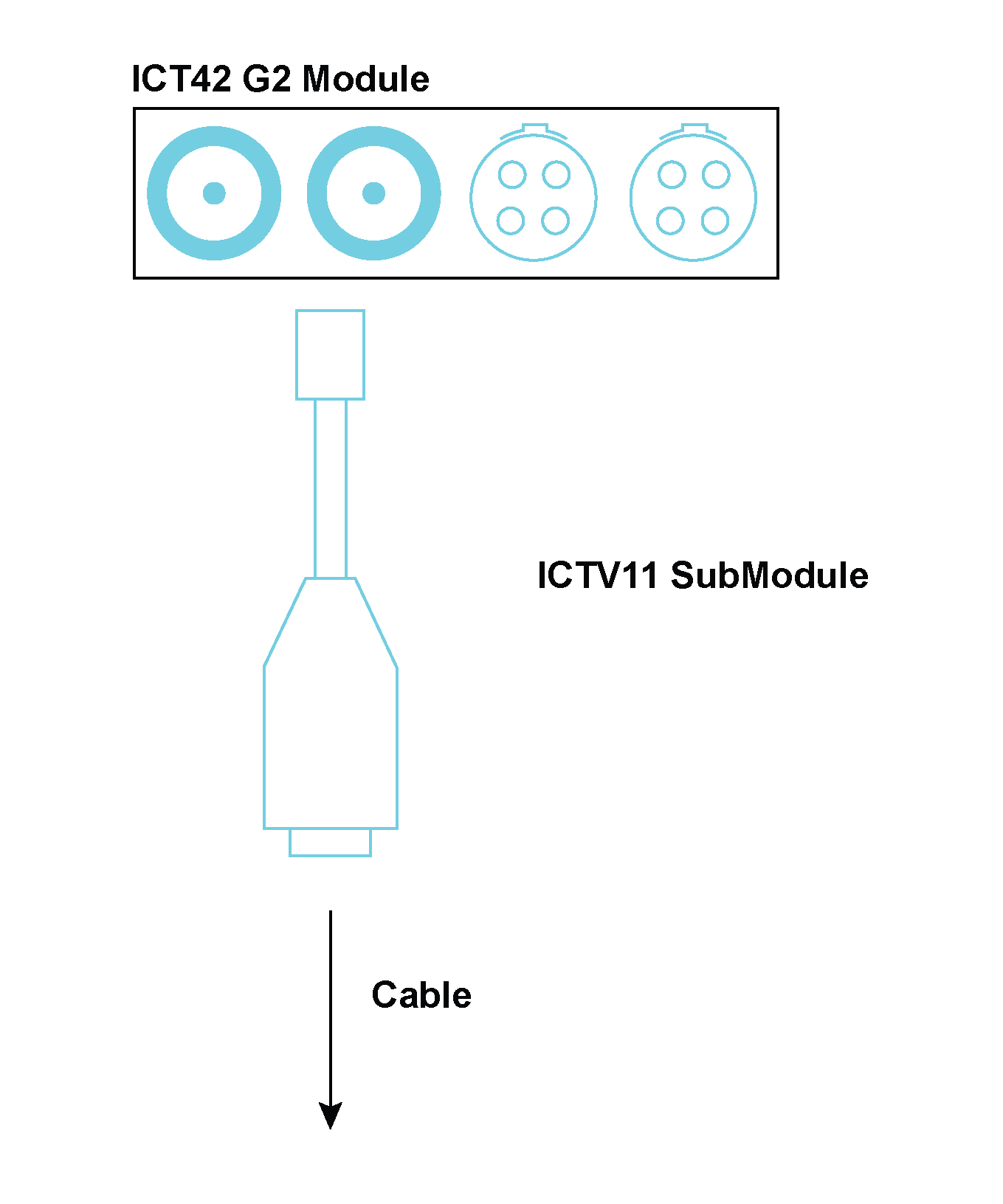
| ICTV11 | A single channel SubModule used with an ICT42 or ICT42S Module. It protects a Tacho channel from high voltages |
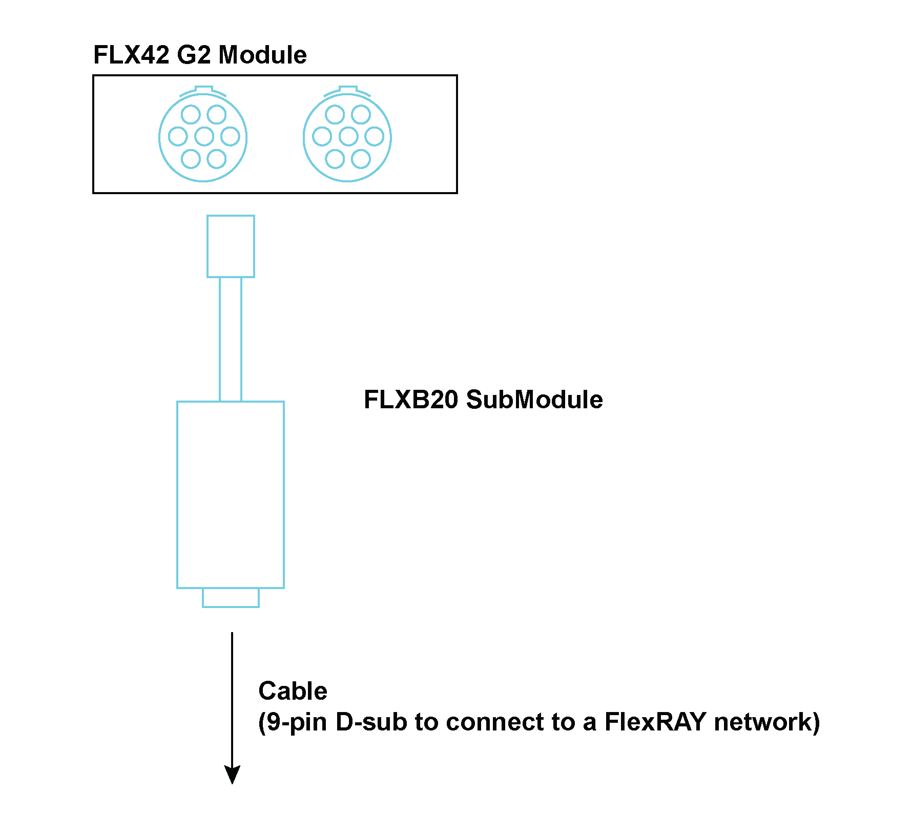
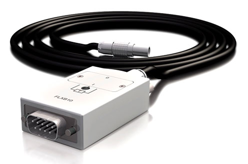
| FLXB20 | A SubModule which connects a FLX42 Module to a FlexRay™ network, or a CAN42 Module to a CANbus network |
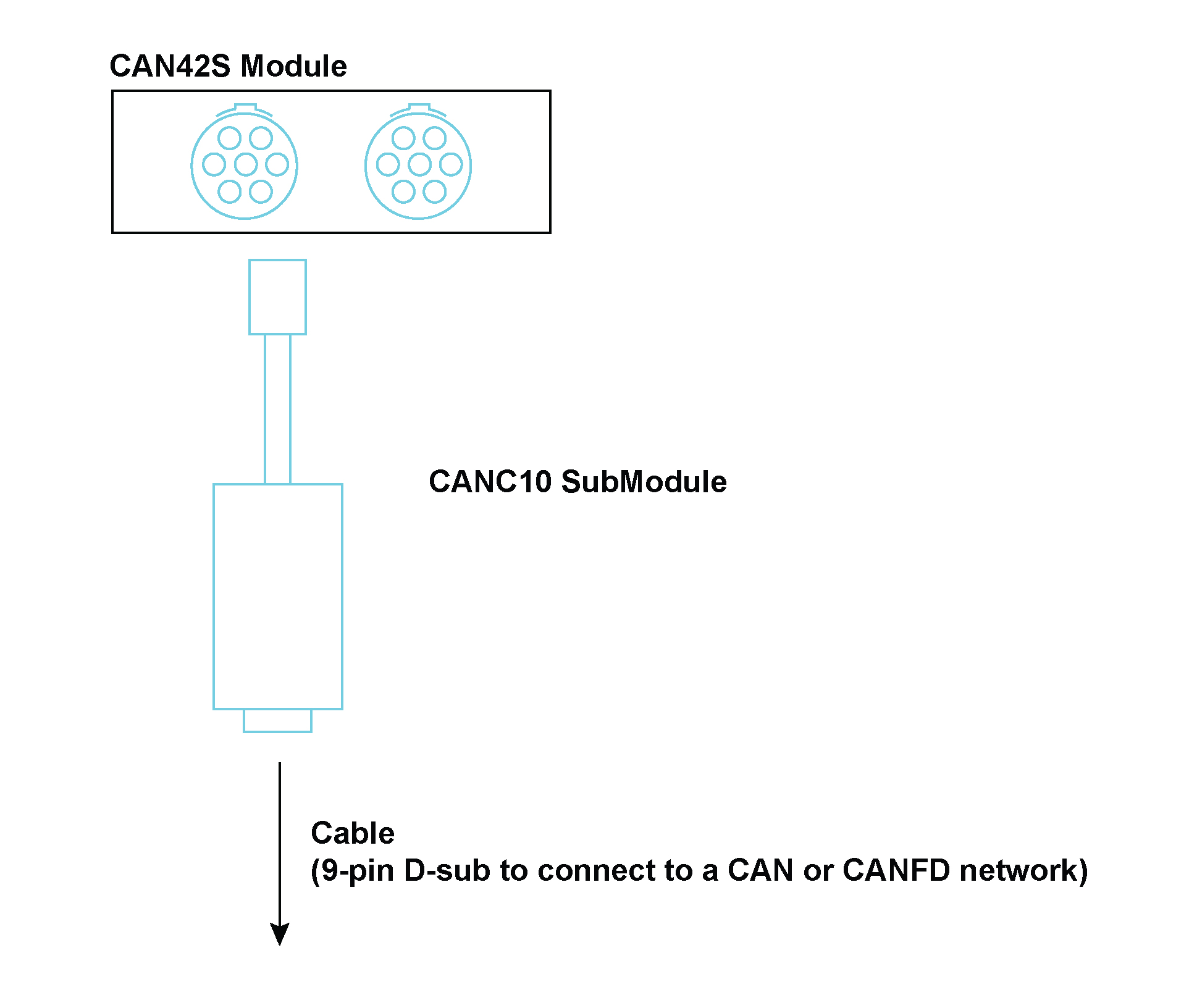
| CANC10 | A SubModule which connects a CAN 42 or CAN42S Module to a CAN or CAN FD bus network |
| SMRM10 | A panel designed to house SubModules |
| THMx10 | A single channel SubModule used with a THM42 Module. It is used to connect two thermocouples to a single channel |
| THMP10 | A single channel SubModule used with a THM42 Module. It is used to connect two Pt100 sensors to a single channel |
| THMS10 | A single channel SubModule used with a THM42 Module. It provides 2 sets of 4-way general purpose screw terminals to connect to a pair of E, J, K or T thermocouples or a pair of Pt100 sensors |
| THMS10/250 | The THMS10/250 SubModule is used in conjunction with a THM42 Module. It converts constant current signals between 4 mA and 20 mA to voltages between 1 V and 5 V |
| QBNC11 | A single channel SubModule used with an ALO42S Module. It is used to expand the capacity of the Modules |
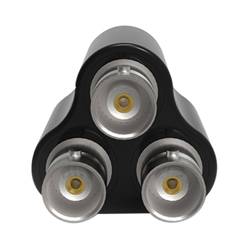
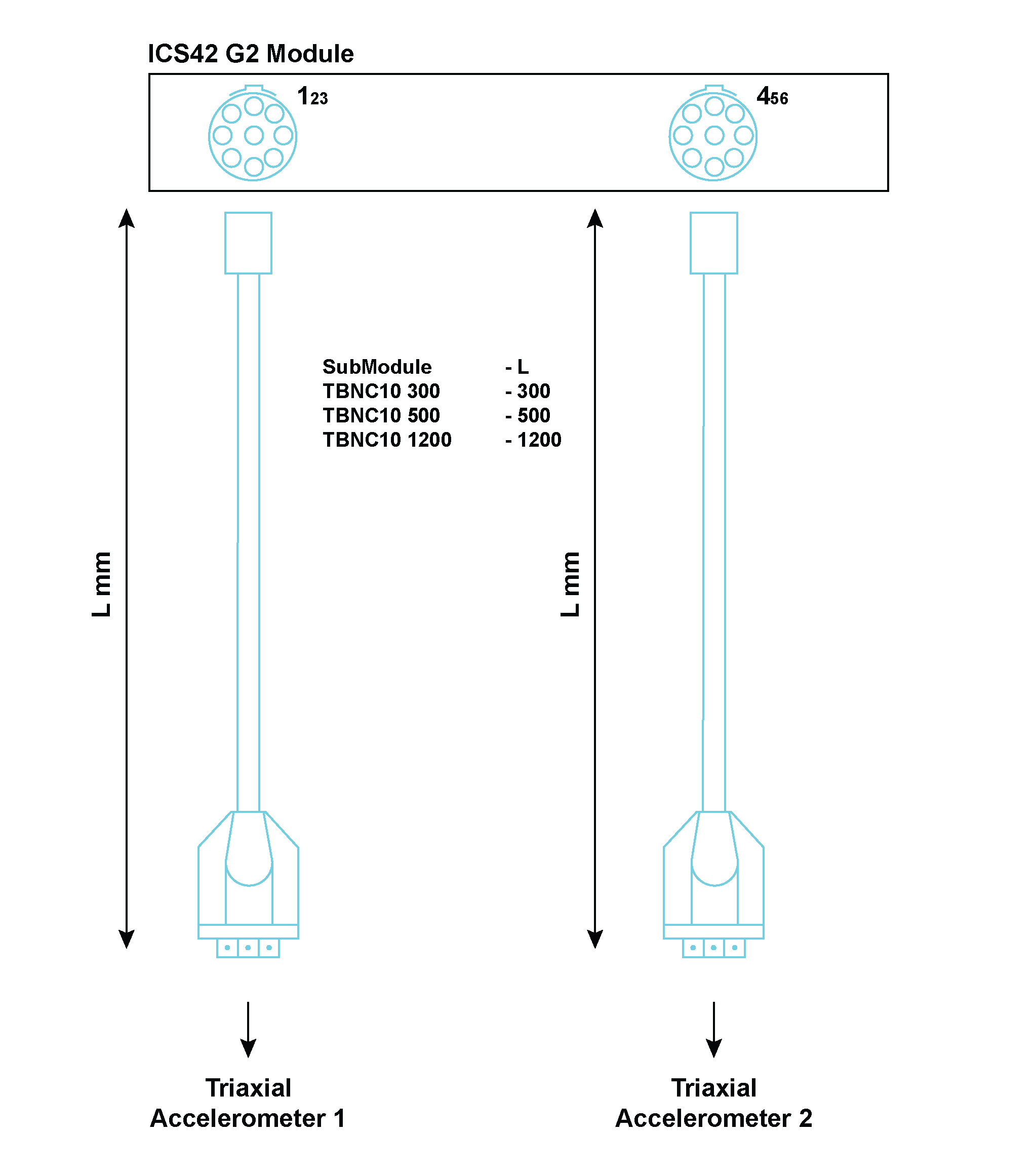
The TBNC10 is used to connect to the ICS42 Module. It splits signals, from a 9-way LEMO® connector on the Module’s front panel, to a single triangular prism with 3 BNC connectors to easily connect sensors. Three BNC connectors are provided on the SubModule to interface to the appropriate triaxial or single axis accelerometer. The SubModule connects to the ICS42 Module through a 300 mm, 500 mm or 1200 mm fly-lead.
| TBNC10 options: | |
|---|---|
| TBNC10 300 | The BNC Jack connectors connect to the ICS42 Module with a total cable length of 300 mm |
| TBNC10 500 | The BNC Jack connectors connect to the ICS42 Module with a total cable length of 500 mm |
| TBNC10 1200 | The BNC Jack connectors connect to the ICS42 Module with a total cable length of 1200 mm |
Where used:
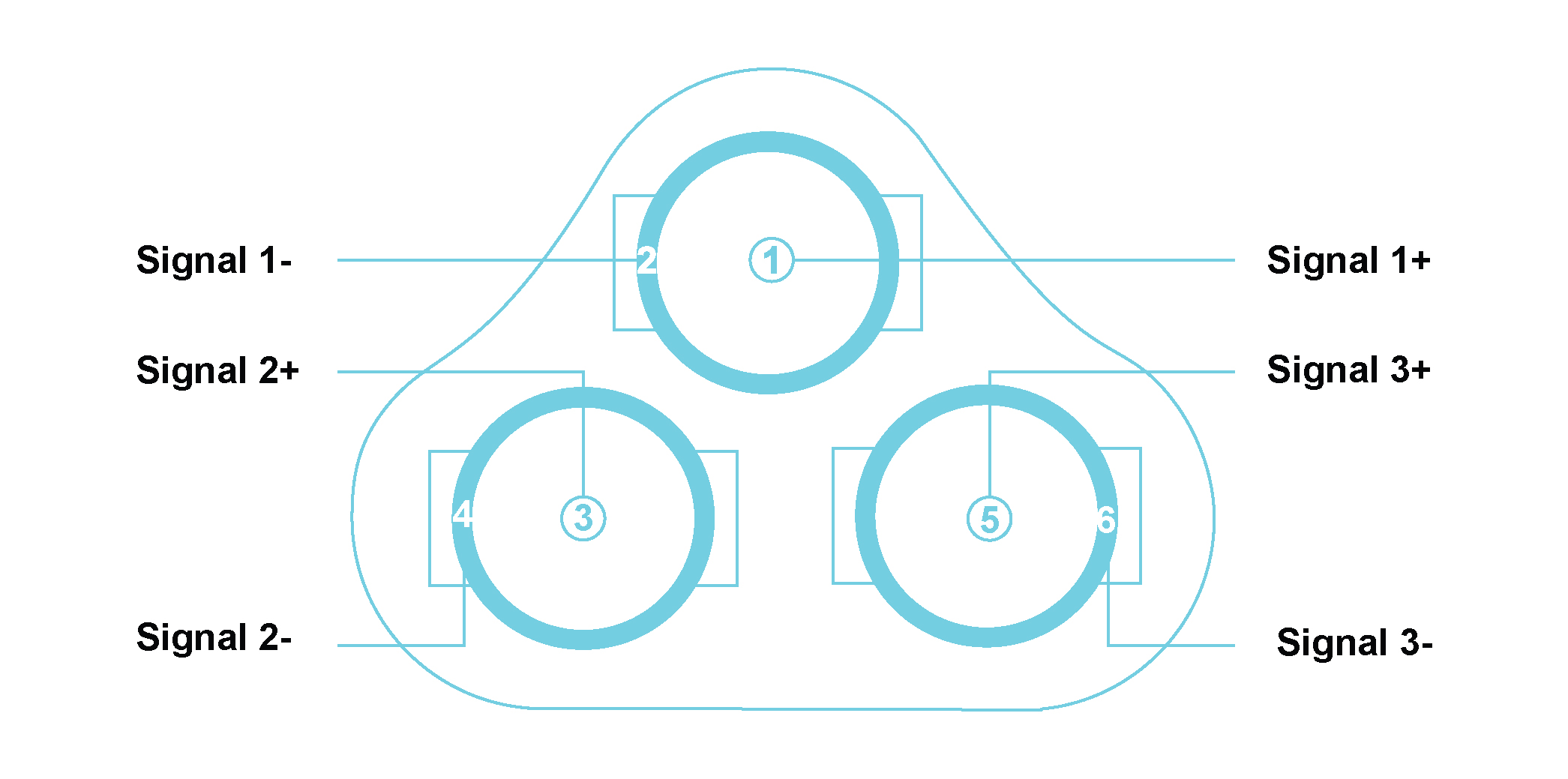
| Pin Number of TBNC10 | Signal Name | Channel on ICS42 | Triaxial Accelerometer pin | |
| Left Lemo® | Right Lemo® | |||
| 1 | Signal 1+ | Channel 1+ | Channel 4+ | X+ |
| 2 | Signal 1- | Channel 1- | Channel 4- | GNDx |
| 3 | Signal 2+ | Channel 2+ | Channel 5+ | Y+ |
| 4 | Signal 2- | Channel 2- | Channel 5- | GNDy |
| 5 | Signal 3+ | Channel 3+ | Channel 6+ | Z+ |
| 6 | Signal 3- | Channel 3- | Channel 6- | GNDz |
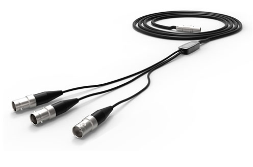
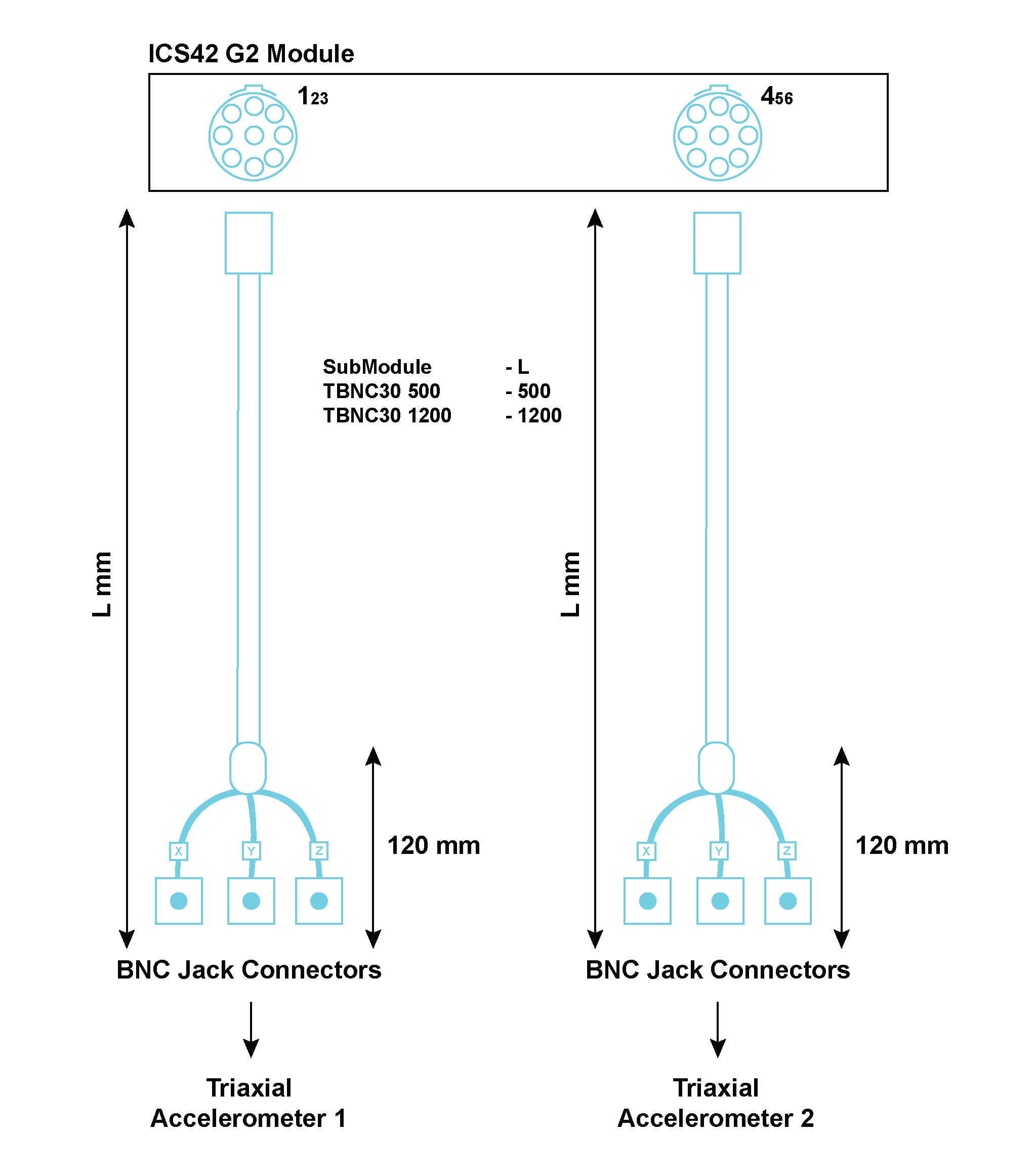
The TBNC30 is used to connect to the ICS42 Module. The Tri-BNC30 SubModule splits signals from a 9-way LEMO® FGG.0B, connecting on the Module’s front panel, to 3 single BNC Jack connectors to easily connect sensors. Three BNC Jack connectors are crimped on cables to provide a flexible interface to the appropriate triaxial or single axis accelerometer. The SubModule connects to the ICS42 Module through a 500 mm or 1200 mm fly-lead.
| TBNC30 options: | |
|---|---|
| TBNC30 500 | The BNC Jack connectors connect to the ICS42 Module with a total cable length of 500 mm |
| TBNC30 1200 | The BNC Jack connectors connect to the ICS42 Module with a total cable length of 1200 mm |
Where used:
| Pin Number of TBNC30 | Signal Name | Channel on ICS42 | Triaxial Accelerometer pin | |
| Left Lemo® | Right Lemo® | |||
| 1 | Signal 1+ | Channel 1+ | Channel 4+ | X+ |
| 2 | Signal 1- | Channel 1- | Channel 4- | GNDx |
| 3 | Signal 2+ | Channel 2+ | Channel 5+ | Y+ |
| 4 | Signal 2- | Channel 2- | Channel 5- | GNDy |
| 5 | Signal 3+ | Channel 3+ | Channel 6+ | Z+ |
| 6 | Signal 3- | Channel 3- | Channel 6- | GNDz |
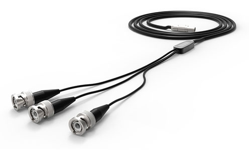
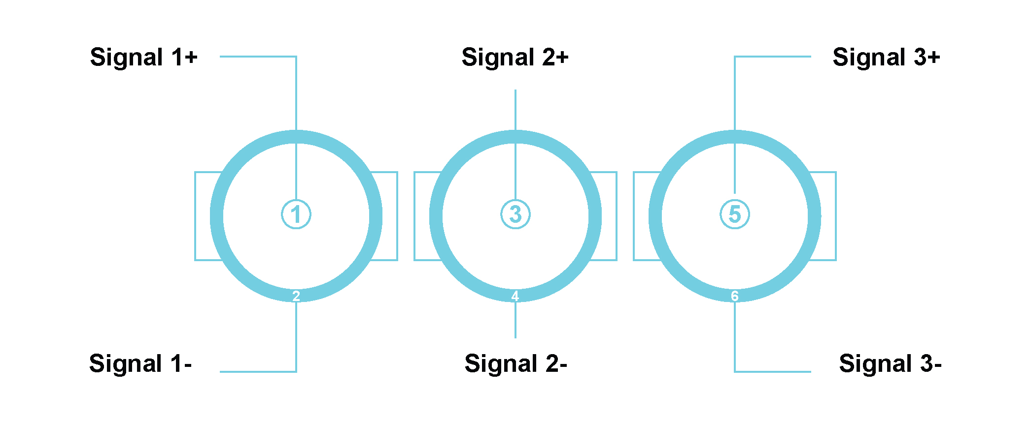
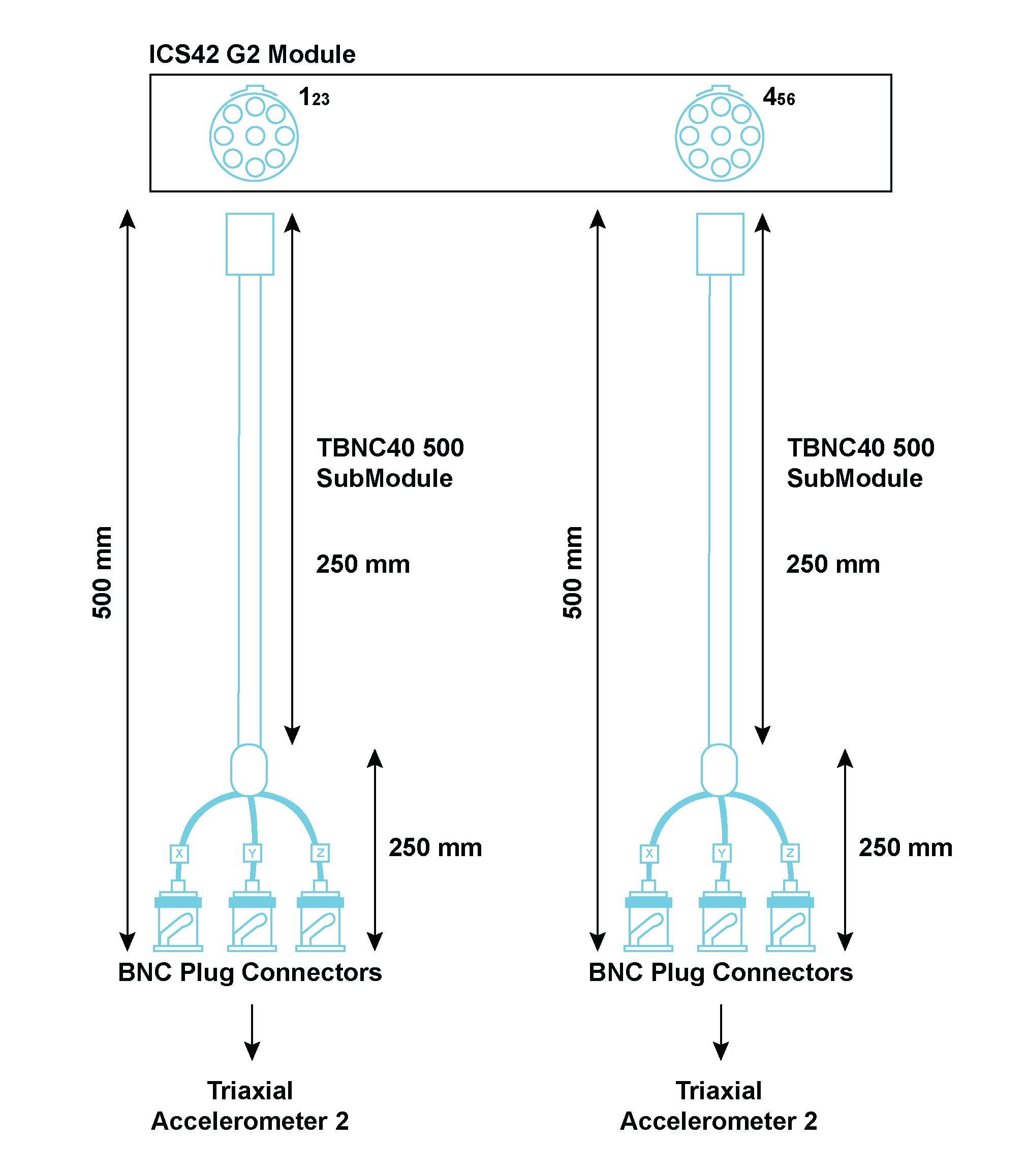
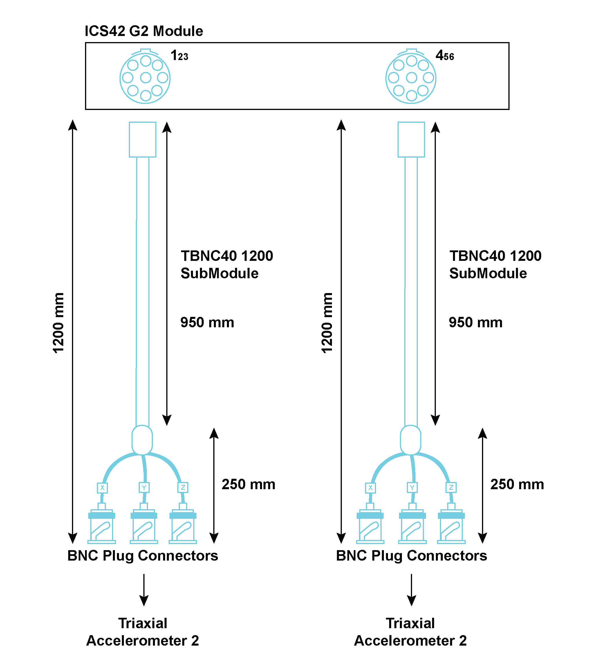
The TBNC40 is used to connect to the ICS42 Module. The Tri-BNC40 SubModule splits signals from a 9-way LEMO® FGG.0B, connecting on the Module’s front panel, to 3 single BNC Plug connectors to easily connect sensors. Three single BNC Plug connectors are crimped on cables to provide a flexible interface to the appropriate triaxial or single axis accelerometer. There are two lengths options available:
| TBNC40 options: | |
|---|---|
| TBNC40 500 | The BNC Plug connectors connect to the ICS42 Module with a total cable length of 500 mm |
| TBNC40 1200 | The BNC Plug connectors connect to the ICS42 Module with a total cable length of 1200 mm |
Where used:
| Pin Number of TBNC40 | Signal Name | Channel on ICS42 | Triaxial Accelerometer pin | |
| Left Lemo® | Right Lemo® | |||
| 1 | Signal 1+ | Channel 1+ | Channel 4+ | X+ |
| 2 | Signal 1- | Channel 1- | Channel 4- | GNDx |
| 3 | Signal 2+ | Channel 2+ | Channel 5+ | Y+ |
| 4 | Signal 2- | Channel 2- | Channel 5- | GNDy |
| 5 | Signal 3+ | Channel 3+ | Channel 6+ | Z+ |
| 6 | Signal 3- | Channel 3- | Channel 6- | GNDz |
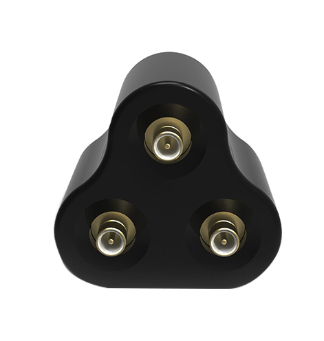
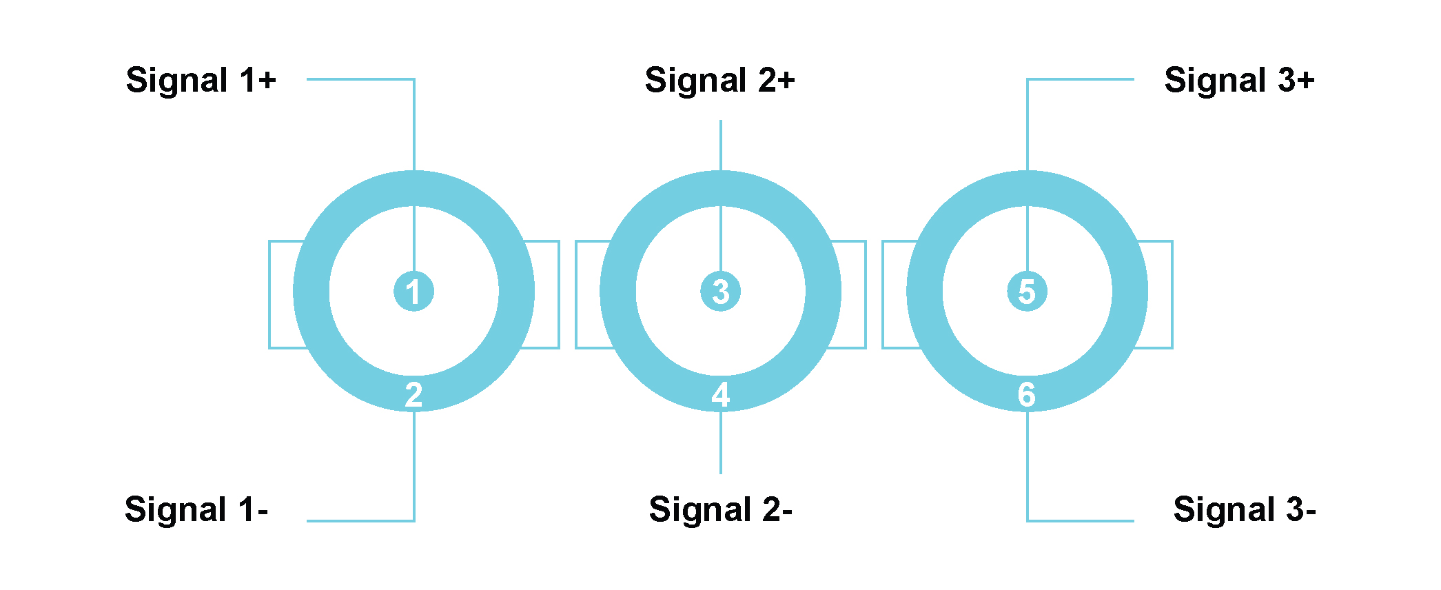
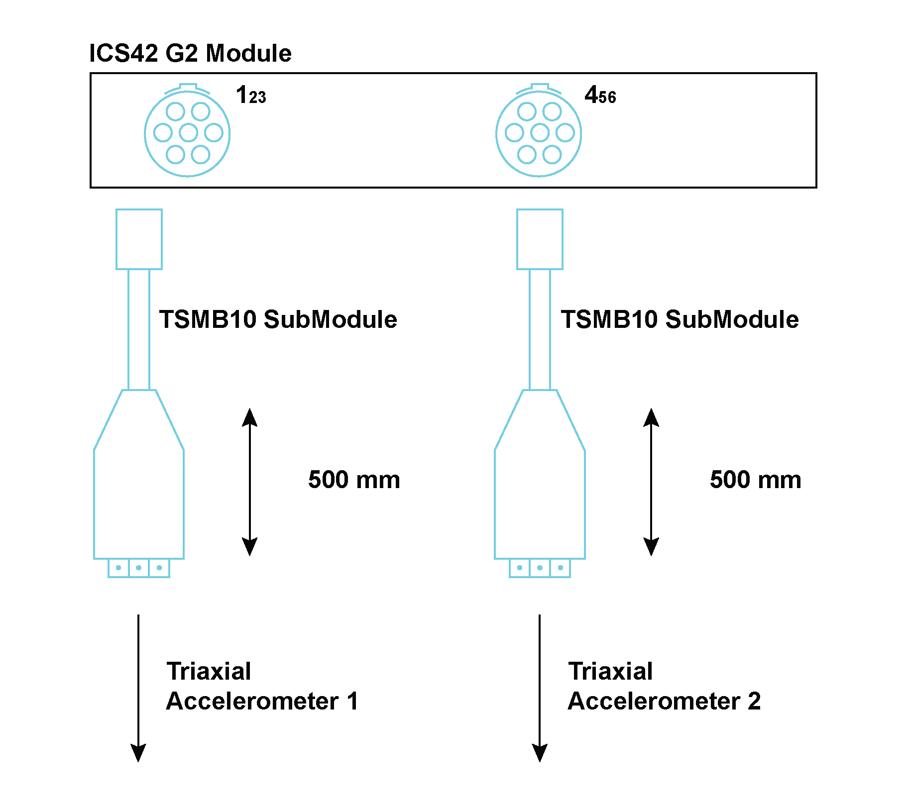
The TSMB10 is used to connect to the ICS42 Module. The Tri-SMB10 SubModule splits signals, from a 9-way LEMO® connector on the Module’s front panel, to 3 SMB connectors to easily connect sensors. Three SMB connectors are provided on the SubModule to interface to the appropriate triaxial or single axis accelerometer. The SubModule connects to the ICS42 Module through a 500 mm or 1200 mm fly-lead.
| TSMB10 options: | |
|---|---|
| TSMB10 500 | The SMB connectors connect to the ICS42 Module with a total cable length of 500 mm |
| TSMB10 1200 | The SMB connectors connect to the ICS42 Module with a total cable length of 1200 mm |
Where used:
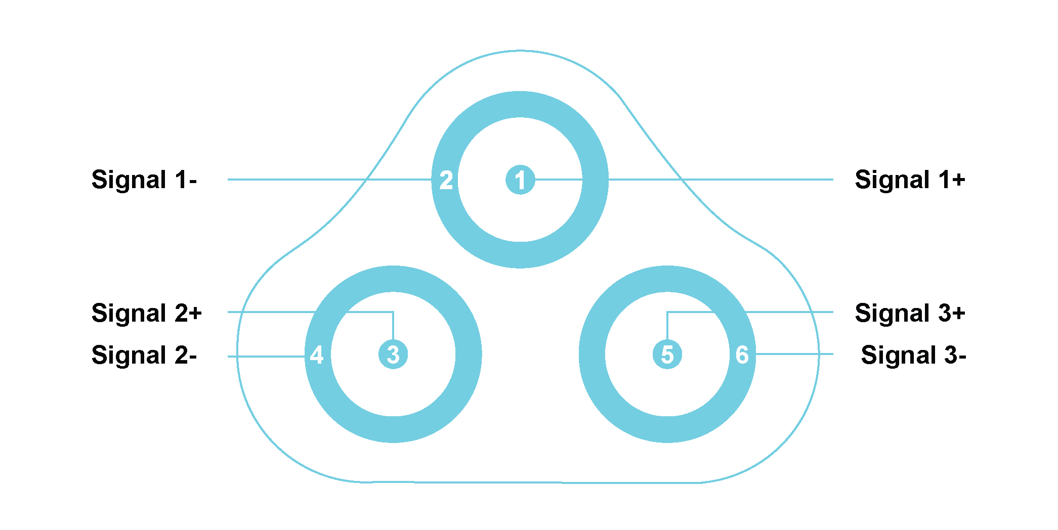
| Pin Number of TSMB10 | Signal Name | Channel on ICS42 | Triaxial Accelerometer pin | |
| Left Lemo® | Right Lemo® | |||
| 1 | Signal 1+ | Channel 1+ | Channel 4+ | X+ |
| 2 | Signal 1- | Channel 1- | Channel 4- | GNDx |
| 3 | Signal 2+ | Channel 2+ | Channel 5+ | Y+ |
| 4 | Signal 2- | Channel 2- | Channel 5- | GNDy |
| 5 | Signal 3+ | Channel 3+ | Channel 6+ | Z+ |
| 6 | Signal 3- | Channel 3- | Channel 6- | GNDz |
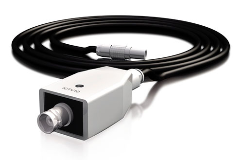
The ICTV11 is used to protect the ICT42 or ICT42S Module’s Tacho inputs from excessively high voltages. These may occur when inductive devices are discharged or when measuring close to high voltage circuitry. The SubModule contains high energy over-voltage dissipation devices. These devices limit the output voltage to reasonable values which will not destroy the internal circuitry of the ICT42 and ICT42S Modules. A BNC connector is provided on the SubModule to interface to the appropriate Tacho sensor. The SubModule connects to the ICT42 and ICT42S Module through a 300 mm fly-lead ending with a 4-pin LEMO® FGG.0B connector.
Where used:


The FLXB20 SubModule provides an interface to a 9-pin D-sub connection. The FLXB20 SubModule is used to connect a FLX42 Module to a FlexRay™ network. It provides the interface between the 7-pin LEMO® connector on the FLX42 Module and the 9-pin D-sub connector on the FlexRay™ network.
Where used (FlexRay™):
The FLXB20 SubModule can also be used to connect a CAN42 Module to a CANbus network. Here it provides the interface between the 7-pin LEMO® connector on the CAN42 Module and the 9-pin D-sub connector on the CANbus network. Where Used (CANbus):

The CANC10 SubModule provides an interface to a 9-pin D-sub connection. The CANC10 SubModule is used to connect a CAN42S Module to a CANbus network. It provides the interface between the 7-pin LEMO® connector on the CAN42S Module and the 9-pin D-sub connector on the CANbus network.
Where used (CANbus):

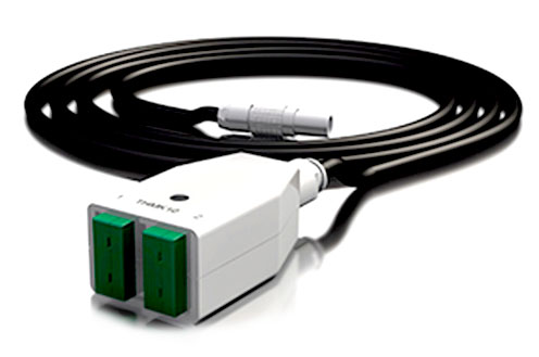
Seven thermocouple-based SubModules exist, each containing dedicated thermocouple connectors. Each SubModule contains a pair of miniature thermocouple connectors, of the appropriate alloy and color, according to either IEC or ANSI standards. Cold-junction-compensation is facilitated through the use of a 0.5 °C accurate temperature sensor in thermal contact with the connectors’ contacts. The SubModule type is identified through a TEDS interface.
Each SubModule connects to the THM42 Module through a 300 mm fly-lead ending with a 7-way LEMO® FGG 0B connector.
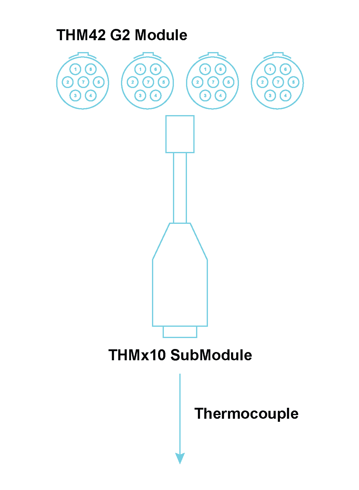
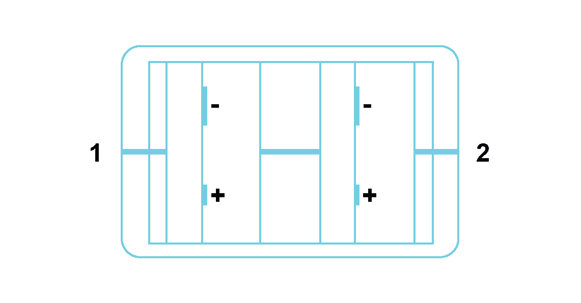
Miniature thermocouple connector 1 (and similarly thermocouple connector 2):
| These 7 SubModules can be listed as follows: | |
|---|---|
 |
The THME10 SubModule contains Chromel/Constantan (NiCr/CuNi) alloys and has lilac connectors (IEC 584-3 and ANSI MC 96.1) |
 |
The THMJ10 SubModule contains Iron/ Constantan (Fe/CuNi) alloys and has black connectors (both IEC 584-3 and ANSI MC 96.1) |
 |
The THMK10 SubModule contains Chromel/Alumel (NiCr/NiAl) alloys and has green connectors (IEC 584-3) |
 |
The THMK10 SubModule contains Chromel/Alumel (NiCr/NiAl) alloys and has yellow connectors (ANSI MC 96.1) |
 |
The THMT10 SubModule contains Copper/Constantan (Cu/CuNi) alloys and has blue connectors (ANSI MC 96.1) |
 |
The THMT10 SubModule contains Copper/Constantan (Cu/CuNi) alloys and has brown connectors (IEC 584-3) |
 |
The THMU10 SubModule contains Copper/Copper (Cu/Cu) alloys and has white connectors |
Seven thermocouple-based SubModules
The THMP10 SubModule is used in conjunction with a THM42 Module to provide 2 sets of 4-way LEMO® EGG 0B connectors for use with 2 Pt100 sensors. These connectors provide current to a Pt100 sensor and sense the voltage across it. The SubModule type is identified through a TEDS interface. The THMP10 SubModule connects to the THM42 Module through a 300 mm fly-lead ending with a 7-way LEMO® FGG 0B connector.
Where used:
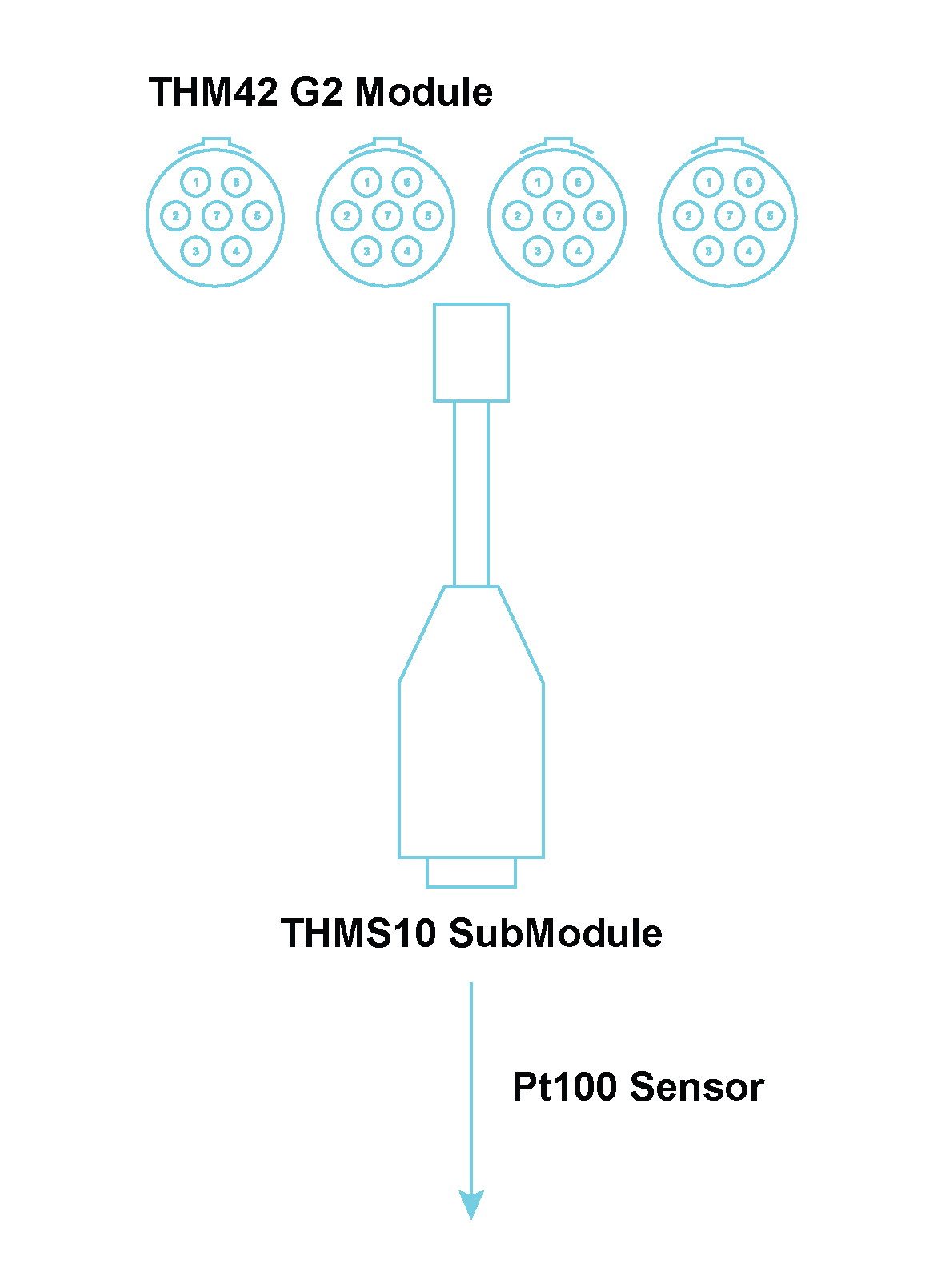
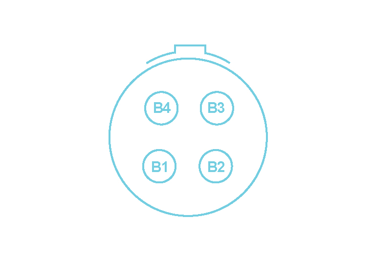
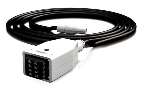
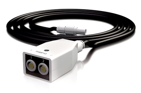
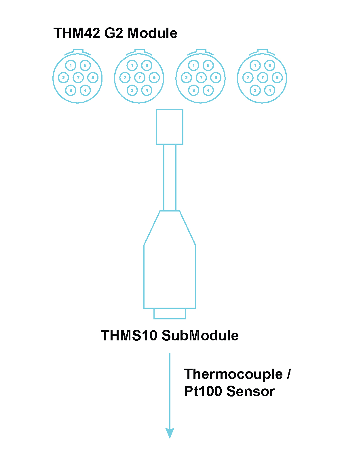
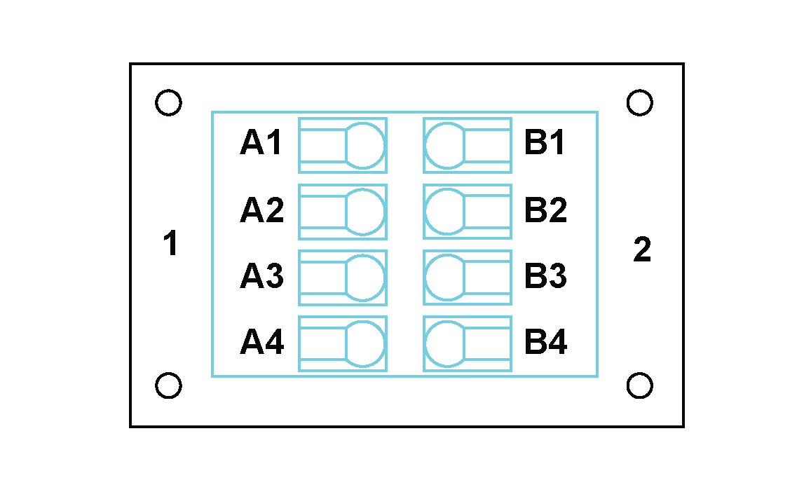
The THMS10 SubModule is used in conjunction with a THM42 Module to provide 2 sets of 4‑way general purpose screw terminals to connect to a pair of E, J, K or T thermocouples or a pair of Pt100 sensors. Cold-junction-compensation is facilitated through the use of a 0.5 °C accurate temperature sensor in thermal contact with the connectors’ contacts. Constant current is provided for Pt100 use. The SubModule type is identified through a TEDS interface. The THMS10 SubModule connects to the or THM42 Module through a 300 mm fly-lead ending with a 7-way LEMO® FGG 0B connector.
Where used:
Note: The use of 2-wire and 3-wire Pt100 sensors is not recommended due to an increase in measurement errors brought about by the lead resistance.
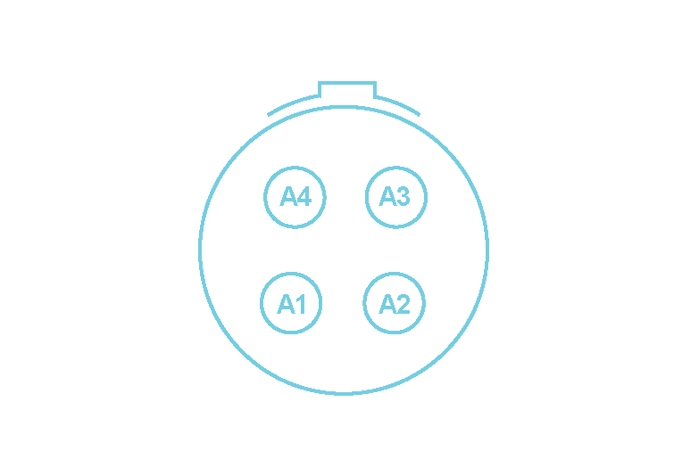
The table below provides a summary of the connection procedures for thermocouples and Pt100 sensors when 2 sensors are being connected to the THMS10.
| Pin Number | Function | Sensor Type | |||
|---|---|---|---|---|---|
| Thermocouple | Pt100 (4-wire) | Pt100 (3-wire) | Pt100 (2-wire) | ||
| A1 | Excitation0+ | NC 2 | Positive current lead of first Pt100 | Positive current lead of first Pt100 | Jumper between pins A1 and A2 3 |
| A2 | Signal0+ | Positive lead of first thermocouple | Positive signal lead of first Pt100 | Positive signal lead of first Pt100 | Positive signal lead of first Pt100 |
| A3 | Signal0- | Negative lead of first thermocouple | Negative signal lead of first Pt100 | Negative signal lead of first Pt100 | Negative signal lead of first Pt100 |
| A4 | Excitation0- | NC | Negative current lead of first Pt100 | Jumper between pins A3 and A4 | Jumper between pins A3 and A4 |
| B1 | Excitation1+ | NC | Positive current lead of second Pt100 | Positive current lead of second Pt100 | Jumper between pins B1 and B2 |
| B2 | Signal1+ | Positive lead of second thermocouple | Positive signal lead of second Pt100 | Positive signal lead of second Pt100 | Positive signal lead of second Pt100 |
| B3 | Signal1- | Negative lead of second thermocouple | Negative signal lead of second Pt100 | Negative signal lead of second Pt100 | Negative signal lead of second Pt100 |
| B4 | Excitation1- | NC | Negative current lead of second Pt100 | Jumper between pins B3 and B4 | Jumper between pins B3 and B4 |
Connections between 2 Thermocouple/Pt100 Sensors and a THMS10
The table below provides a summary of the connection procedures for thermocouples and Pt100 sensors, when 1 sensor is being connected to channel 1 of the THMS10.
| Pin Number | Function | Sensor Type | |||
|---|---|---|---|---|---|
| Thermocouple | Pt100 (4-wire) | Pt100 (3-wire) | Pt100 (2-wire) | ||
| A1 | Excitation0+ | NC4 | Positive current lead of Pt100 | Positive current lead of Pt100 | Jumper between pins A1 and A2 5 |
| A2 | Signal0+ | Positive lead of thermocouple | Positive signal lead of Pt100 | Positive signal lead of Pt100 | Positive signal lead of Pt100 |
| A3 | Signal0- | Negative lead of thermocouple | Negative signal lead of Pt100 | Negative signal lead of Pt100 | Negative signal lead of Pt100 |
| A4 | Excitation0- | NC | NC | NC | NC |
| B1 | Excitation1+ | NC | NC | NC | NC |
| B2 | Signal1+ | NC | NC | NC | NC |
| B3 | Signal1- | NC | NC | NC | NC |
| B4 | Excitation1- | NC | Negative current lead of Pt100 | Jumper between pins A3 and B4 | Jumper between pins A3 and B4 |
Connections between 1 Thermocouple/Pt100 Sensor and channel 1 of the THMS10
The table below provides a summary of the connection procedures for thermocouples and Pt100 sensors, when 1 sensor is being connected to channel 2 of the THMS10.
| Pin Number | Function | Sensor Type | |||
|---|---|---|---|---|---|
| Thermocouple | Pt100 (4-wire) | Pt100 (3-wire) | Pt100 (2-wire) | ||
| A1 | Excitation0+ | NC 6 | Positive current lead of Pt100 | Positive current lead of Pt100 | Jumper between pins A1 and B2 7 |
| A2 | Signal0+ | NC | NC | NC | NC |
| A3 | Signal0- | NC | NC | NC | NC |
| A4 | Excitation0- | NC | NC | NC | NC |
| B1 | Excitation1+ | NC | NC | NC | NC |
| B2 | Signal1+ | Positive lead of thermocouple | Positive signal lead of Pt100 | Positive signal lead of Pt100 | Positive signal lead of Pt100 |
| B3 | Signal1- | Negative lead of thermocouple | Negative signal lead of Pt100 | Negative signal lead of Pt100 | Negative signal lead of Pt100 |
| B4 | Excitation1- | NC | Negative current lead of Pt100 | Jumper between pins B3 and B4 | Jumper between pins B3 and B4 |
Connections between 1 Thermocouple/Pt100 Sensor and channel 2 of the THMS10
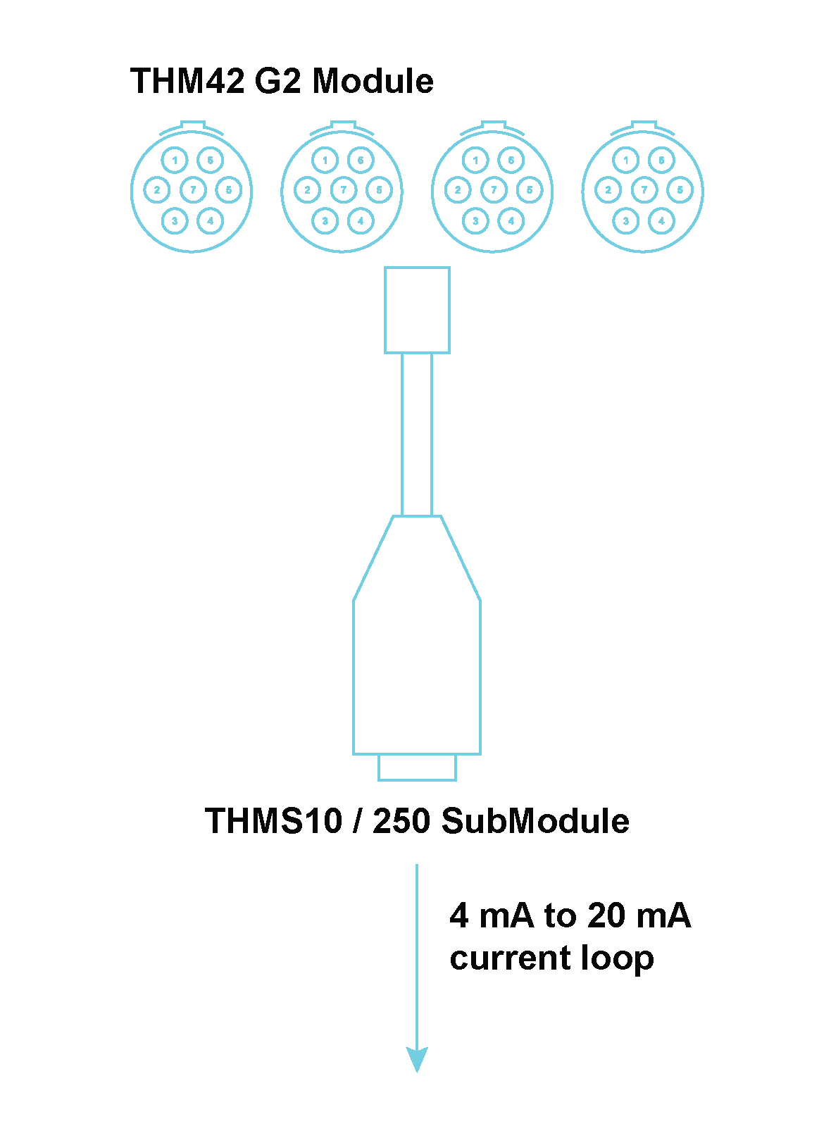
The THMS10/250 SubModule is used in conjunction with a THM42 Module to provide 2 sets of 4‑way general purpose screw terminals to connect to two constant current signals from sensors between 4 mA and 20 mA. Two precision 250 Ω resistors convert the constant current signals to voltage signals between 1 V and 5 V. The SubModule is identified through a TEDS interface. The THMS10/250 SubModule connects to the THM42 through a 300 mm fly-lead ending with a 7-way LEMO® FGG 0B connector.
Where used:
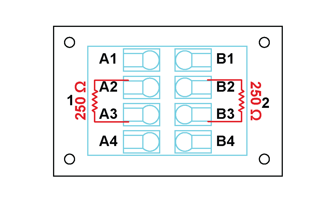
Note: The 250 Ω resistor is internal in the THMS10/250 and the user should not add the resistor to the pins.
The table below provides a summary of the connection procedures for sensors with a 4 mA to 20 mA current output that are being connected to the THMS10/250.
| Pin Number | Function | Sensor with 4 mA to 20 mA current output |
|---|---|---|
| A1 | Excitation0+ | NC 8 |
| A2 | Signal0+ | Positive lead of first sensor |
| A3 | Signal0- | Negative lead of first sensor |
| A4 | Excitation0- | NC |
| B1 | Excitation1+ | NC |
| B2 | Signal1+ | Positive lead of second sensor |
| B3 | Signal1- | Negative lead of second sensor |
| B4 | Excitation1- | NC |
Connections between two 4 mA to 20 mA output current sensors and a THMS10/250
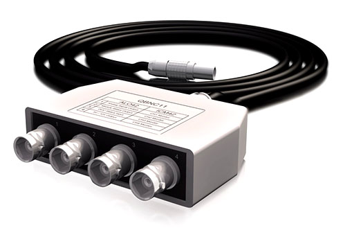
The Quad BNC (QBNC) is a SubModule that is used to split signals from a 7-pin LEMO® connector to 4 BNC connectors. A sticker on top indicates with which Modules the QBNC is compatible, and how the signals are mapped.
Where used:
Splits the signals coming from an ALO42S Module
Designed as a SubModule used to expand the capacity of an ALOP42S Module
Accepts one 7-pin LEMO® FGG 0B connector
Provides 4 BNC connectors to split the signals as follows:
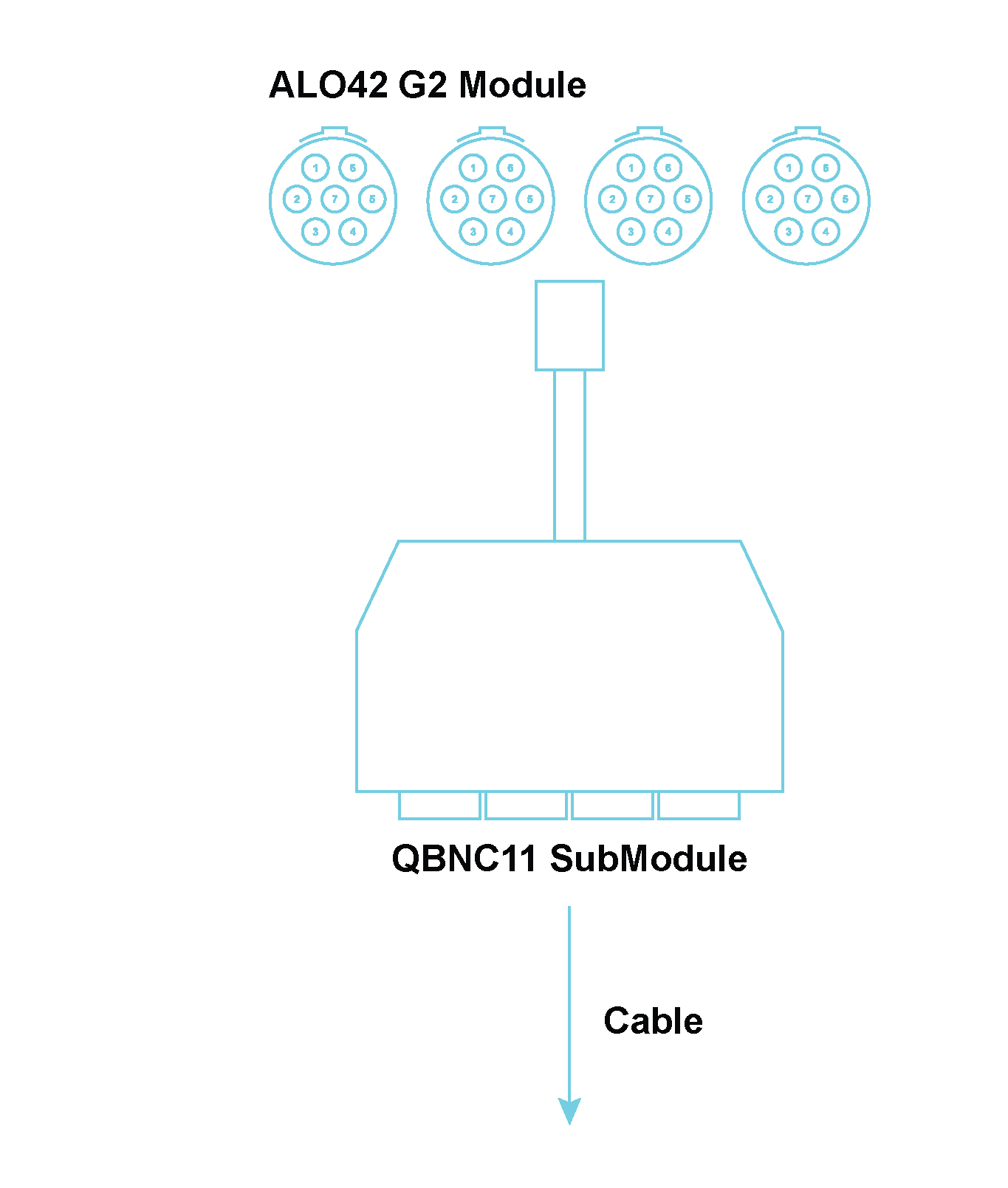

QBNC11 Pinouts when connected to an ALO42S Module
| Description | The 218K is a variable length power cable for powering the MICROQ |
|---|---|
| Connector 1 | 2-way LEMO® (FGG.0B.302) |
| Connector 2 | Banana and Dolphin Adapter |
| Length | Variable |
| Current Rating | 10 A |
| Description | The 217K is a variable length power cable for powering the MICROQ (MICROQ to Delta) |
|---|---|
| Connector 1 | 2-way LEMO® (FGG.0B.302) |
| Connector 2 | Banana plug |
| Length | Variable |
| Current Rating | 20 A |
| Description | The 211K is a standard length power cable for powering the
MICROQ from a cigarette lighter (MICROQ automotive cable) |
|---|---|
| Connector 1 | 2-way LEMO® (FGG.0B.302) |
| Connector 2 | Cigarette adapter |
| Length | 1 m |
| Current Rating | 7.5A |
| Description | The 219K is a variable length power cable for powering the MICROQ from a cigarette lighter. |
|---|---|
| Connector 1 | 2-way LEMO® (FGG.0B.302) |
| Connector 2 | Cigarette adapter |
| Length | Variable (custom) |
| Current Rating | 10 A |
For ICP42, ICT42, IRG42
| Description | The 025K is a standard length signal cable that converts the SMB output of a QModule to a BNC output |
|---|---|
| Connector 1 | SMB socket |
| Connector 2 | BNC plug |
| Length | 1 m |
For ICP42S, ICT42S
| Description | The 029K is a standard length signal cable that converts the 3-pin LEMO® output of a QModule to a BNC output |
|---|---|
| Connector 1 | 3-pin LEMO® (EHG.0B) |
| Connector 2 | BNC plug |
| Length | 1 m |
For CHG42S
| Description | The 013K is a standard length cable that connects a CHG42S to a BNC socket |
|---|---|
| Connector 1 | 10-32 Microdot |
| Connector 2 | BNC plug |
| Length | 1 m |
For ICT42, ICT42S
| Description | The 031K is a standard length signal cable that converts the 4-pin LEMO® output of a QModule to a BNC output |
|---|---|
| Connector 1 | 4-pin LEMO® (EHG.0B) |
| Connector 2 | BNC plug |
| Length | 1 m |
For WSB42, WSB42X, ALI42
| Description | The 001K is a standard length sensor cable used to connect deflection bridge sensors to WSB42 and WSB42X Modules. Also compatible with ALI42 Modules |
|---|---|
| Connector 1 | 7-way LEMO® (FGG.0B.307) with blue bend relief |
| Connector 2 | 7 unconnected wires (brown, red, orange, yellow, green, blue, black) |
| Length | 2 m |
Note: The 001K cable is also available as the 008K cable, with variable lengths (customizable according to preference)
For ALI42, ALO42S, WSB42, WSB42X
| Description | The 046K is a standard length signal cable that converts the 7-pin LEMO® output of a QModule to a BNC output |
|---|---|
| Connector 1 | 7-way LEMO® (FGG.0B.307) |
| Connector 2 | BNC plug |
| Length | 1 m |
For MIC42X
| Description | The 044K is a standard length signal cable that converts the 7-pin LEMO® output of a QModule to a BNC output |
|---|---|
| Connector 1 | 7-way LEMO® (EGG.1B) |
| Connector 2 | BNC plug |
| Length | 1 m |
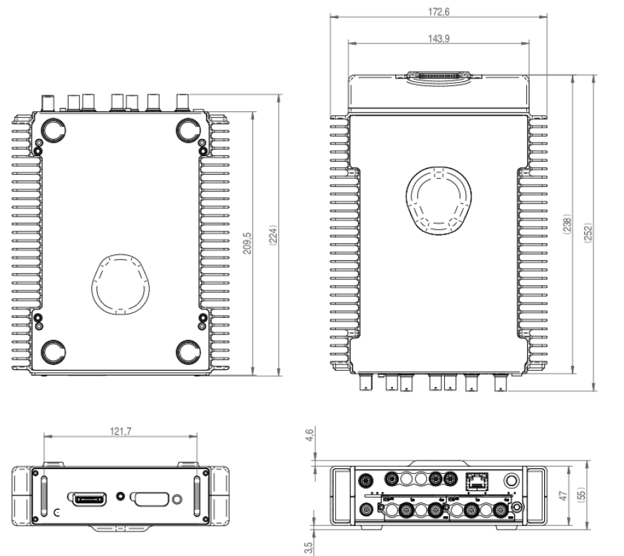
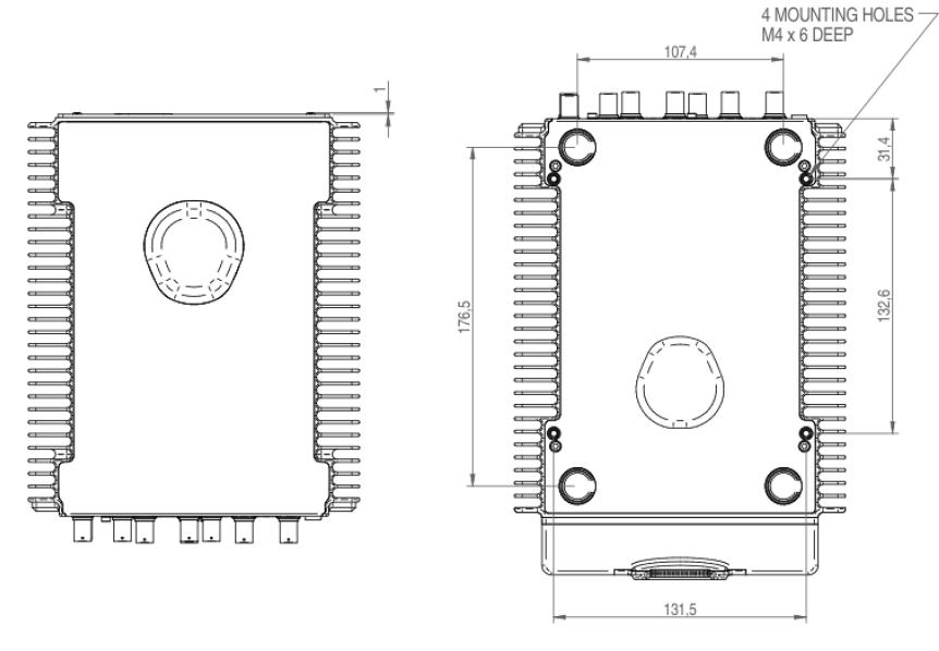
The MICROQ has four mounting holes on its bottom face.
| Parameter | Value |
|---|---|
| Hole Size | M4 Mounting Holes, 6mm deep |
| Maximum shear/force applied to fastening screws | 250 N |
| Spacing between mounting holes running from the front to the rear | 132.6 mm |
| Spacing between left and right sets of mounting holes | 131.5 mm |
| General | |
|---|---|
| Maximum Dimensions (W x L x H) | 172 x 251 x 53 mm (6.77 x 9.88 x 2 “) |
| Weight without built-in Internal MICROQ Battery | 1.85 kg (4.08 lbs) |
| Weight with built-in Internal MICROQ Battery | 2.25 kg (4.96 lbs) |
| Weight with Attached External MICROQ Battery | 2.70 kg (5.95 lbs) |
| Shock | 40 g of shock with 11 ms duration |
| Vibration | 0.1 g2/Hz from 10 to 2000 Hz |
| Earthing Connector Type | 4 mm jack |
| Operating Temperatures | -20 °C to 50 °C |
| Operating Humidity | 5 % - 90 % RH |
| Ingress Protection Rating | IP40 |
| Typical Mounting | Table top |
| Ground Connector Type | 4 mm Jack |
| Maximum Internal Frequency | 1.25 GHz |
| MICROQ Power Supply Input | |
| Power over Ethernet | |
| Type | Power over Ethernet (PoE) IEEE 802.3at Type 2, LTPoE++ |
| Voltage | 42 VDC – 57 VDC |
| Max Power Input | 40 W |
| Typical Power Consumption | 25 - 30 W |
| DC Power | |
| Type | DC Power |
| Voltage | 10 VDC – 30 VDC |
| Max Power Input | 40 W |
| Recommended Power Supply | Mean Well GST120A24 |
| Ethernet | |
| Type | 1000BASE-T |
| Harmonized Item Description and Coding System | |
| HS Tariff Code | 9031 |
All rights are reserved. No part of this publication may be reproduced, shared with a third party, stored in a retrieval system or transmitted in any form (mechanical, electronic, photocopying, recording or other) without the prior written permission of Mecalc. All information in this document, including drawings, technical descriptions and images, remains the property of Mecalc.
Every precaution has been taken to provide the most relevant and accurate information regarding the products discussed in this manual. However, as Mecalc is constantly improving and updating its products, this information is subject to change without notice.
Extended warranty options are available, please contact your supplier for more information.
Mecalc shall not be responsible for conformity with any standards, codes or regulations that may apply to the combination of products in the customer’s application or use of the products.
At the customer’s request Mecalc can provide applicable certification documents identifying ratings and limitations of use that apply to products. However, this information by itself is not sufficient for a complete determination of the suitability of the products in combination with the end product, machine, system or other application or use.
The following are examples of typical applications. However, this is neither an exhaustive list nor intended to imply that products will always be suitable for use in these instances:
Please know and observe all prohibitions of use applicable to the products.
Note: Never use the products for an application involving serious risk to life or property without ensuring that the system as a whole has been designed to address the risks, and that the Mecalc products are properly rated and installed for the intended use within the overall equipment or system.
Mecalc cannot be responsible for any consequences as a result of the user’s programming of a programmable product.
Performance data given in this manual are provided as a guide for the user in determining suitability and do not constitute a warranty. The data may represent the results of Mecalc ’s test conditions and users will have to correlate those results with actual application requirements. Actual performance is subject to the Mecalc Warranty and Limitations of Liability.
The information in this manual has been carefully checked and is believed to be accurate. However, no responsibility is assumed for clerical, typographical or proofreading errors or omissions.
These features and specifications may not be included based on the software package utilized with the MICROQ.↩︎
Not connected↩︎
The jumper connection is not made by the THMS10 internally and must therefore be made by the user externally↩︎
Not connected↩︎
The jumper connection is not made by the THMS10 internally and must therefore be made by the user externally↩︎
Not connected↩︎
The jumper connection is not made by the THMS10 internally and must therefore be made by the user externally↩︎
Not connected↩︎
![]()
© Mecalc (Pty) Ltd. QuantusSeries and the Q icon are registered trademarks of Mecalc (Pty) Ltd. Information is provided "as is" without warranties or guarantees regarding accuracy, completeness, or suitability for any purpose. Mecalc assumes no liability for its use. In keeping with our commitment to continuous product improvement, information contained herein is subject to change.