DATA SHEET
The industry’s first 5 MSa/s 24-bit digitizer for Pyroshock applications. Two channels supporting Bridge, ICP® and voltage inputs equipped with sophisticated anti-alias filtering. Includes buffered analog output channel and advanced options for synchronisation and triggering.
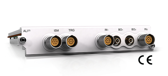
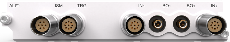
ALI25 MODULE
The ALI25 is a high-bandwidth Module designed for triggered/burst acquisition for Pyro-Shock / Mechanical Shock applications.
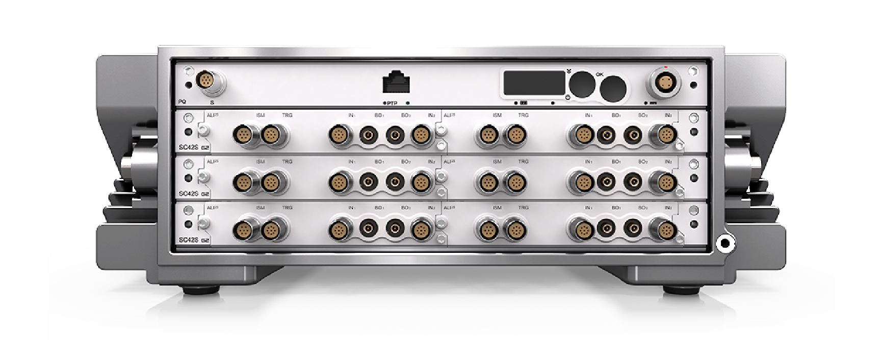
Every channel is equipped with precise anti-alias filtering on the Signal and Sense lines, along with dedicated bridge signal conditioning. In addition, each channel features a 24-bit, 5 MSa/s ADC and a 21 MSa data buffer. Systems can be configured with 2 to over 1000 channels.
Measurement Integrity and Sensor Status prior to an event is verified with continuous: pre-trigger monitoring, summarized signal information, and sensor fault detection. Built-in Signal Conditioning for bridge-type transducers and voltage signals. Constant voltage or current excitation is programmable for each channel.
Each input channel has a buffered low-noise output channel for monitoring or acquiring sensor data via a secondary system. Measurements are triggerable by signal level and persistence, external events, data flow, or software command. This advanced set of triggering options supports multi-system synchronisation and ensures event detection.
Where Used
- Acquisition of Pyro-Shock / Mechanical Shock events related to impact / shock, ballistics, and explosives test.
- Bridge and Resistive Sensors that require 2-wire, 4-wire and 6-wire configurations.
- High Voltage SubModule for external high-voltage signal conditioning used in power measurements.
- Hopkinson Bar Testing
Front Panel and Connectors
Note: All connectors are shown as if looking into the front panel’s connector or at the rear of the cable’s connector.
Analog Input Channels
Overview
2 channels
24-bit resolution, 5 MSa/s sampling rate per channel
Bandwidth:
- DC – 1.0 MHz ±0.1 dB at 5 MSa/s
- DC – 2.375 MHz -3 dB at 5 MSa/s
Modes of operation
- Voltage input mode
- ICP® mode 4 mA to 20 mA with 30 V compliance
- Bridge Input Mode:
- 2-wire plus Shield
- 4-wire plus Shield, targeting Pyro-Shock applications
- 6-wire plus Shield
- Constant Current Mode
Input Ranges
- ±(5, 2.5, 1.25) V, ±(680, 340, 160, 80, 40, 20, 10) mV
Accuracy
- ±0.1% of full scale ±50 µV
Slew Rate
- >50 V/µs
Memory
- 21 M Samples per channel, 24-bit
Differential Input
- Input impedance 2 MΩ Differential, 1 MΩ to GND
Coupling
- DC or AC coupled
CMRR
- DC – 100 Hz, > 85 dB
CM Voltage Range
- ±9 V including signal
Crosstalk
- >90 dB isolation (channel to channel)
Sense ADC
- Continuous fault detection of the excitation lines to detect open / short circuits.
- The ALI25 can support other applications that require more than the 4-wire Pyro-Shock applications.
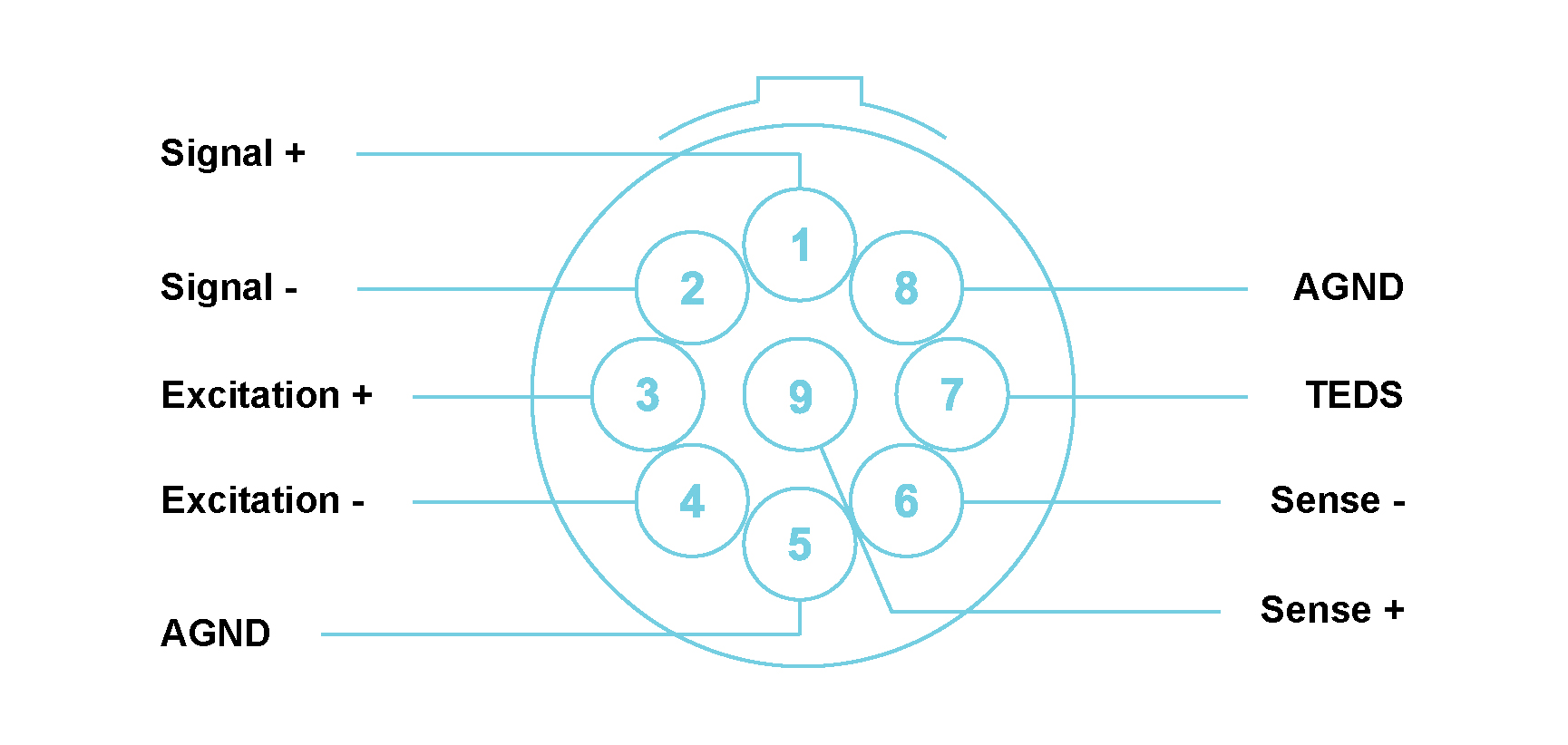
Connectors
- 9-pin LEMO® 0B.309 (one per input channel).
- Signal+, Signal-, Excitation+, Excitation-, Sense+, Sense-. TEDS
(Class 1 & 2), AGND (REF GND),
CGND.
- Separate shield through the housing or pin of the breakout cable connector (9-pin LEMO® to D-Sub 15).
Functions
Offset Control using DAC, ±2.5 V 16-bit resolution
Offset Zero
- Software selectable Autozero routine sets ADC output to zero for a given input.
- Can use a combination of the offset null DAC and digital correction.
Bridge Balancing
- Current injection ±1 mA
- Offset Nulling ±2.5 V, 16-bit DAC
- Bridge balancing activation available through software command
Excitation Voltage and Current (16-bit DAC)
- Differential DC 0 to ±10 V (20 V between Excitation+ & Excitation-), current monitored (limited to 90 mA per channel)
- Bipolar Constant Current Excitation
- 0 to ±30 mA Constant Current
- 4-wire & 2-wire mode
Bridge Voltage insertion
- 10 kΩ resistor may be connected to either signal arm of the bridge and is driven by a 16-bit programmable DAC. Simulated shunt resistors.
Health Check and Calibration Options
- Programmable Internal Reference, 16-bit DAC voltage ±5 V
- Gain Calibration. Accomplished using internal multiple precision voltage references.
- Calibrated Reference Ladder matched to input range
- Full path can be calibrated System to System including buffered output channel path.
- External Calibration through DCAT ISO17025 certified system.
Sensing
- Local | Remote | None (Pyro-Shock 4-wire applications)
Filtering
3 Stages of anti-aliasing (AA) filters:
- Analog AA (AAA) Filtering: Provides a -0.1 dB bandwidth of 2.5 MHz with minimal passband ripple and over 100 dB attenuation for high-frequencies
- Delta-Sigma ADC: Over-samples the signal 8 times and achieves a flat passband of up to 1.7 MHz, anti-alias filter ripple of less than ±0.00002 dB, and stopband attenuation of 86 dB
- FIR Filters: Ensure exceptional signal integrity with a maximum passband ripple of 0.0005 dB and minimum stopband attenuation exceeding 125 dB
The ADC and FIR filters auto-track the ALI25’s decimation factor, providing optimized performance across varying data rates.
Output data rates (ODR) of: (5, 2.5, 1.25) MSa/s, (500, 250, 125, 50, 25, 12.5, 5, 2.5, 1.25) kSa/s
ALI25 FILTER CHARACTERISTICS
| Sample Rate (Sa/s) | Passband (Hz) | Rejection Band (Hz) | Atten. (dB) |
|---|---|---|---|
| 5.0 M |
2.4 M |
2.9 M |
>86 |
| 2.5 M |
1.2 M |
1.45 M |
>86 |
| 1.25 M |
600 k |
725 k |
>100 |
| 500 k |
243 k |
275 k |
>100 |
| 250 k |
121.5 k |
137.5 k |
>100 |
| 125 k |
60.7 k |
68.75 k |
>100 |
| 50 k |
24.3 k |
27.5 k |
>100 |
| 25 k |
12.15 k |
13.75 k |
>100 |
| 12.5 k |
6.075 k |
6.875 k |
>100 |
| 5 k |
2.43 k |
2.75 k |
>100 |
| 2.5 k |
1.215 k |
1.375 k |
>100 |
| 1.25 k |
607 |
687 |
>100 |
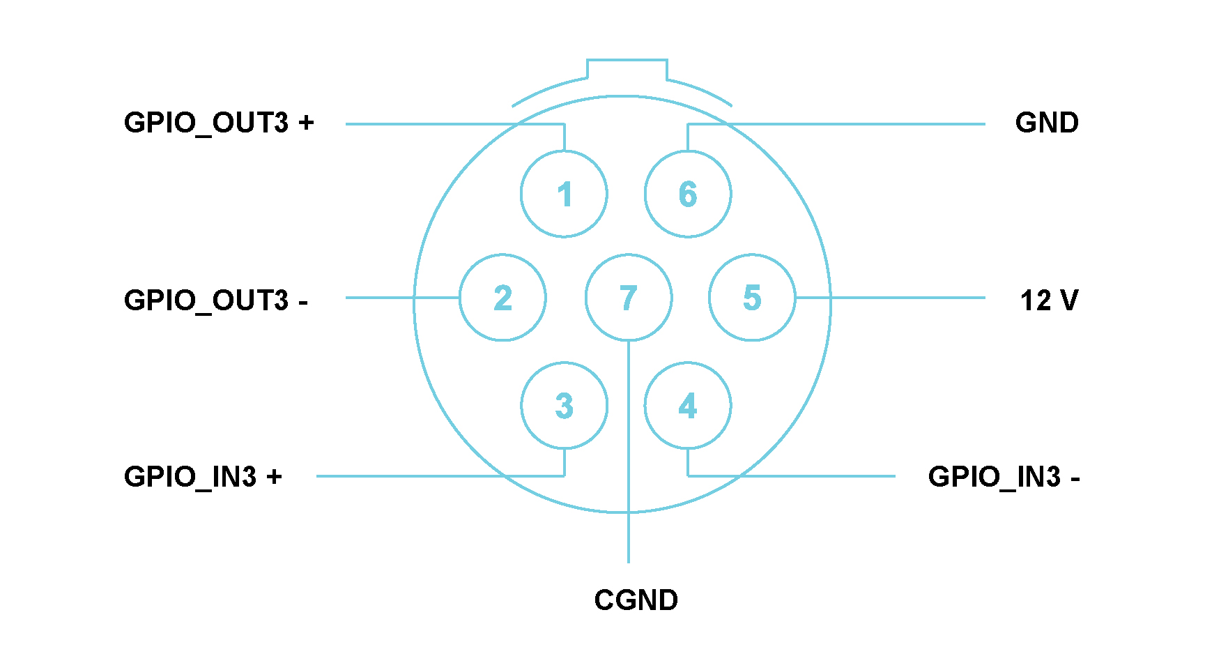
DIGITAL INTERFACE
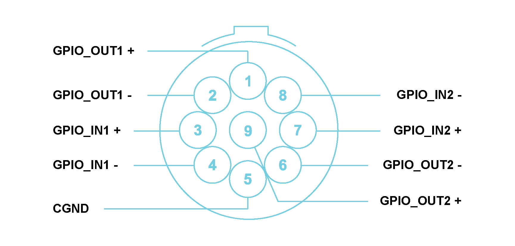
GPIO_IN1, GPIO_IN2, GPIO_IN3, GPIO_OUT0, GPIO_OUT1, GPIO_OUT2, 12 V, PWR_IN, GND (non-isolated PWR), 6 x GPIO (3 x IN, 3 x OUT)
- 5 V compliant, 3.3 V operation
- Communication interface to SubModules
- Can be configured as TRIG input / output (different combinations possible)
- Can be used for SYNC input / output
- Can output a CLK signal
- Can support communication over long cables with a SubModule
12 V, PWR_IN, GND (non-isolated)
- PWR signals that can be used by ISM / PSM for processor and relay control
- Can be used with SubModule to convert / adapt Digital interface for various requirements
- ISM / PSM can be locally powered if far away from the main system
- ISM / PSM detection; if present communication can read back the ID to identify the type
Trigger Options
- Software Trigger, triggered by a software command
- Data Flow Trigger, programmable data trigger
- External Trigger, triggered by external pulse
- Real Time Trigger, trigger when analog input signal reached and remains above programmable limit
- Backplane Trigger (4 lines)
- Synchronous snapshot monitoring of data blocks in parallel to RAM memory
- Synchronous monitoring across all channels while system is running
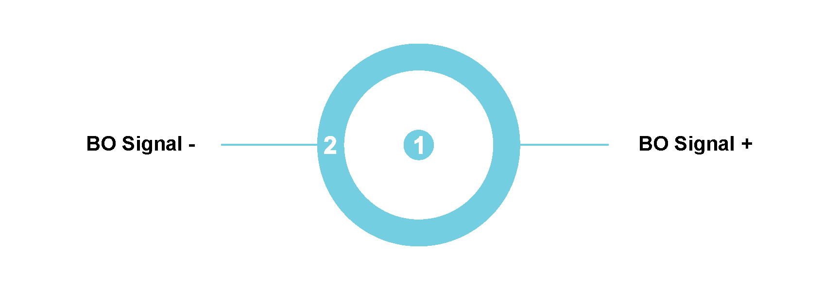
Buffered Analog Output Channels
2 channels
Buffered Analog Output Channel for each Analog Input Channel. Provides a conditioned analog output signal for monitoring with a secondary acquisition system
±1.25 V into 50 Ω for a full-scale input signal
Related Cables, SubModules and Accessories
Cables
CS-ALI-A-DB15 500 (056K 500)
- Breakout Signal Cable 500 mm (converts the 9-pin LEMO® connector to D-Sub 15)
CS-ALI-A-DB15 2000 (056K 2000)
- Breakout Signal Cable 2000 mm (converts the 9-pin LEMO® connector to D-Sub 15)
CS-ALI-T-DB15 500 (058K 500)
- Breakout Digital I/O Cable 500 mm (converts the 9-pin LEMO® connector to D-Sub 15)
CS-ALI-T-DB15 2000 (058K 2000)
- Breakout Digital I/O Cable 2000 mm (converts the 9-pin LEMO® connector to D-Sub 15)
CS-ALI-T-2J 500 (068K 500)
- Breakout Digital Trigger I/O Cable 500 mm (converts the 9-pin LEMO® connector to 2 BNC connectors)
CS-ALI-T-2J 1000 (068K 1000)
- Breakout Digital Trigger I/O Cable 1000 mm (converts the 9-pin LEMO® connector to 2 BNC connectors)
CS-ALI-TF-5J 200 (069K 200)
- Breakout Digital 5x Trigger I/O Cable 200 mm (converts the D-Sub 15 connector to 5 BNC connectors, Fanout cable for SM-ALI-TFCA-DB15)
CS-ALI-A-9L-BNCP 2000 (076K 2000)
- Breakout Signal Cable (Single-ended) 2000 mm (converts the 9-pin LEMO® connector to BNC connector)
CS-ALI-A-DB15M-BNCP-2000 (077K 2000)
- Breakout Signal Cable (Single-ended) 2000 mm (converts the D-Sub 15 connector of 056K to BNC connector)
CS-ALI-A-SMB-BNCP 1000 (038K 1000)
- Breakout Buffer Analog Output Cable 1000 mm (converts the SMB connector to BNC connector)
Submodules
SM-ALI-TFCA-DB15 500
- Trigger Fanout SubModule 500 mm (converts the 9-pin LEMO® connector to D-Sub 15)
SM-ALI-SALI10 TYPE K, T
- Thermocouple to Voltage SubModule with 290 kHz bandwidth (converts the D-Sub 15 for Thermocouple Type K and T)
SM-ALI-SALI20 TYPE J
- Thermocouple to Voltage SubModule with 290 kHz bandwidth (converts the D-Sub 15 for Thermocouple Type J)
SM-ALI-SALI30-HS TYPE K,T
- Thermocouple to Voltage SubModule with 1 MHz bandwidth (converts the D-Sub 15 for Thermocouple Type K and T)
Accessories
RM-ALI-NALI10-20 (PIPS)
- 19 inch RackMount Kit to secure 20x D-Sub 15 connectors in one panel
RM-ALI-NALI10-16 (PIPS)
- 19 inch RackMount Kit to secure 16x D-Sub 15 connectors in one panel